CNC Milling & Vacuum Forming: Oregon Topographic Map
Creating a 3D topographic map of Oregon using CNC milling and post-processing with vacuum forming
Project Overview
This week focused on subtractive manufacturing using CNC milling and post-processing through vacuum forming. I designed and fabricated a 3D topographic map of Oregon, my home state, using the ShopBot CNC mill to carve deep relief features into laminated MDF blocks. The project combined digital fabrication with traditional post-processing techniques to create both the original wooden piece and a vacuum-formed plastic replica.
CNC Milling
- •ShopBot CNC mill with 1/8" bit
- •30mm maximum depth carving
- •Laminated MDF stock material
- •Fusion 360 CAM toolpaths
Vacuum Forming
- •White plastic sheet material
- •Detailed feature retention
- •Challenging demolding process
- •Post-processing technique
Design: Oregon Topographic Map
3D Model
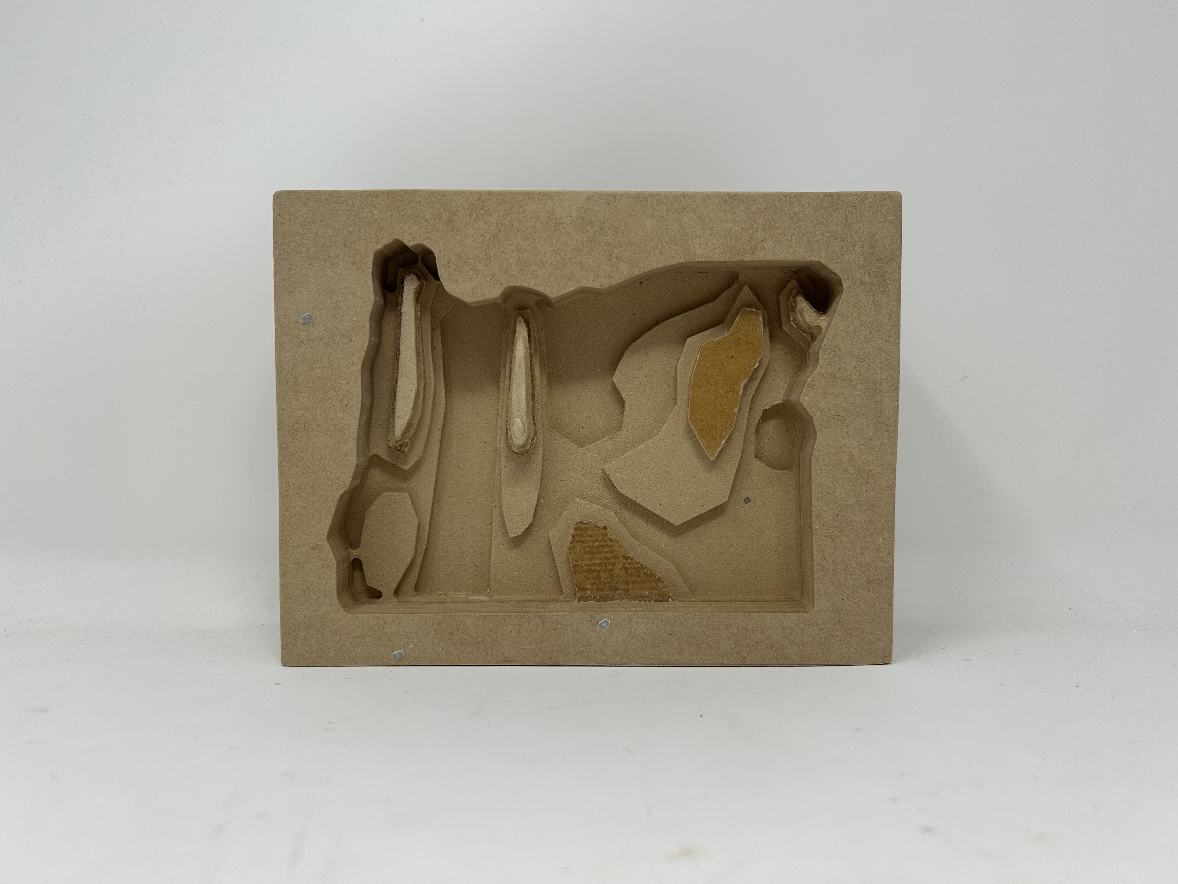
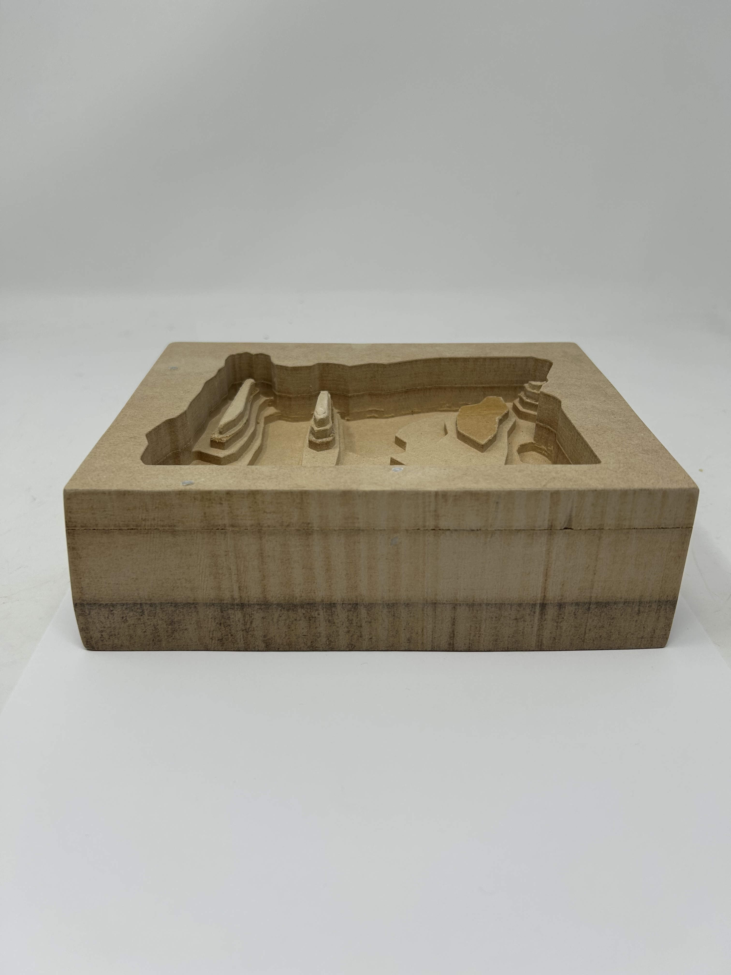
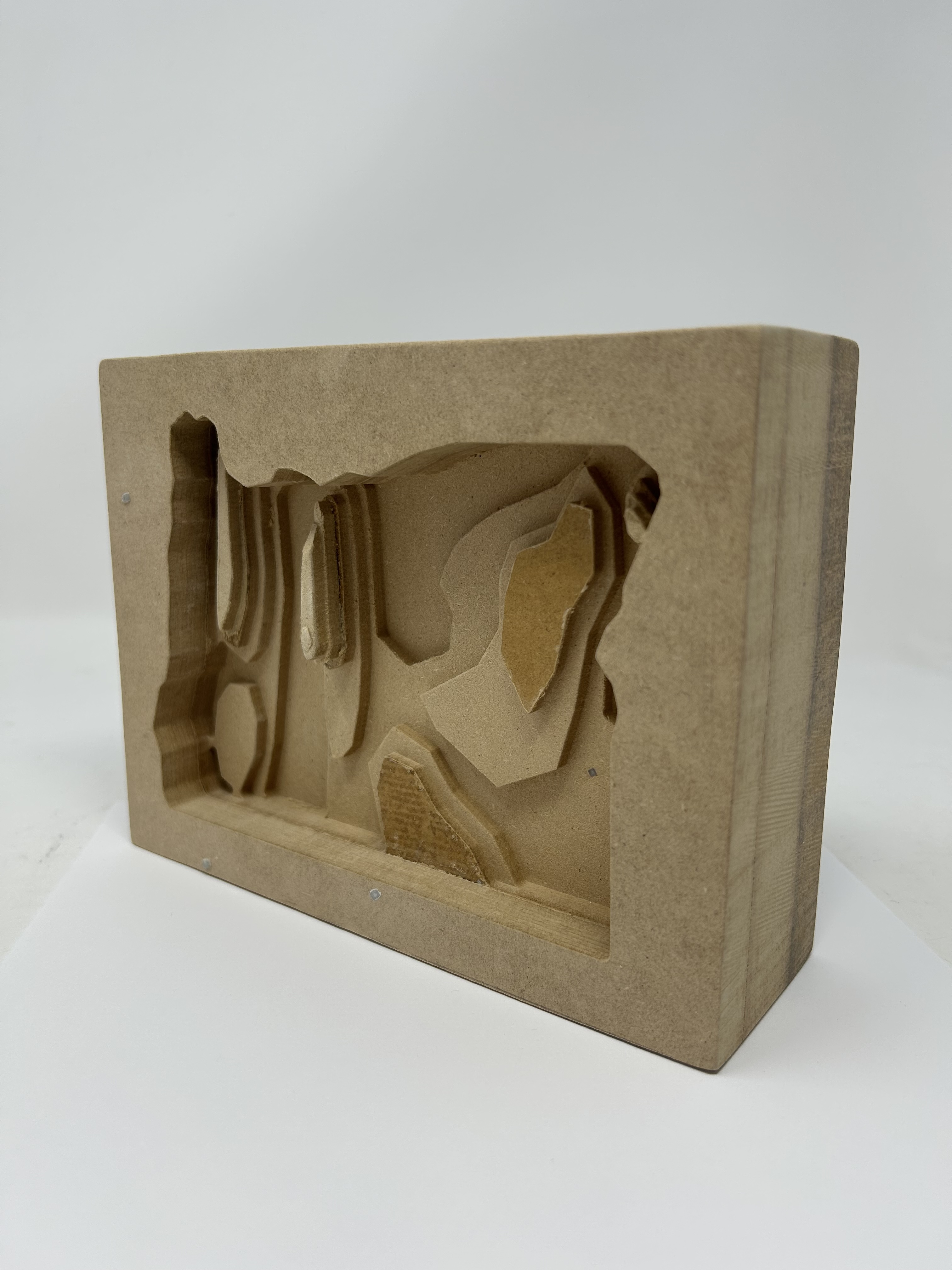
The design features a detailed topographic representation of Oregon, capturing the state's diverse terrain from the Pacific coastline to the Cascade Mountains and high desert regions. The model was designed to be milled as a deep relief carving, with elevation changes represented by depth variations up to 30mm.
Interactive 3D model of Oregon topographic map
Design Considerations
- Material Preparation: Laminated multiple MDF blocks together to achieve sufficient thickness for the 30mm deep carving
- CAM Software: Initially attempted Aspire but found it too complex; switched to Fusion 360 CAM for better control and easier toolpath generation
- Tooling: Used 1/8" end mill for detailed carving while maintaining reasonable machining time
- Stock Size: Oversized stock to allow for bandsaw trimming after milling
CNC Milling: ShopBot Fabrication
Milled Wood Block
The Oregon topographic map was milled on the ShopBot CNC using a 1/8" end mill. The laminated MDF stock provided a stable, uniform material for the deep 30mm carving. After milling, the excess material was trimmed using a bandsaw to create the final piece with clean edges following Oregon's state boundaries.
Front view showing topographic relief
Angled view highlighting depth variation
Side view showing 30mm maximum depth
Fabrication Process
Material Preparation
Glued multiple MDF blocks together to create a stock thick enough for the 30mm deep relief carving. Ensured proper clamping and curing time for a solid lamination.
CAM Programming
Initially attempted to use Aspire for CAM but found the interface and workflow challenging. Switched to Fusion 360 CAM, which provided better control over toolpaths and more intuitive 3D adaptive clearing strategies for the deep pockets.
ShopBot Milling
Machined the piece using a 1/8" end mill on the ShopBot. The smaller bit size allowed for detailed feature resolution while still being robust enough for the deep cuts. Multiple passes were required to reach the full 30mm depth.
Post-Milling Trimming
After milling, used the bandsaw to trim the excess stock material around the Oregon outline, creating clean edges that follow the state boundaries.
Post-Processing: Vacuum Forming
Vacuum Formed Plastic Replica
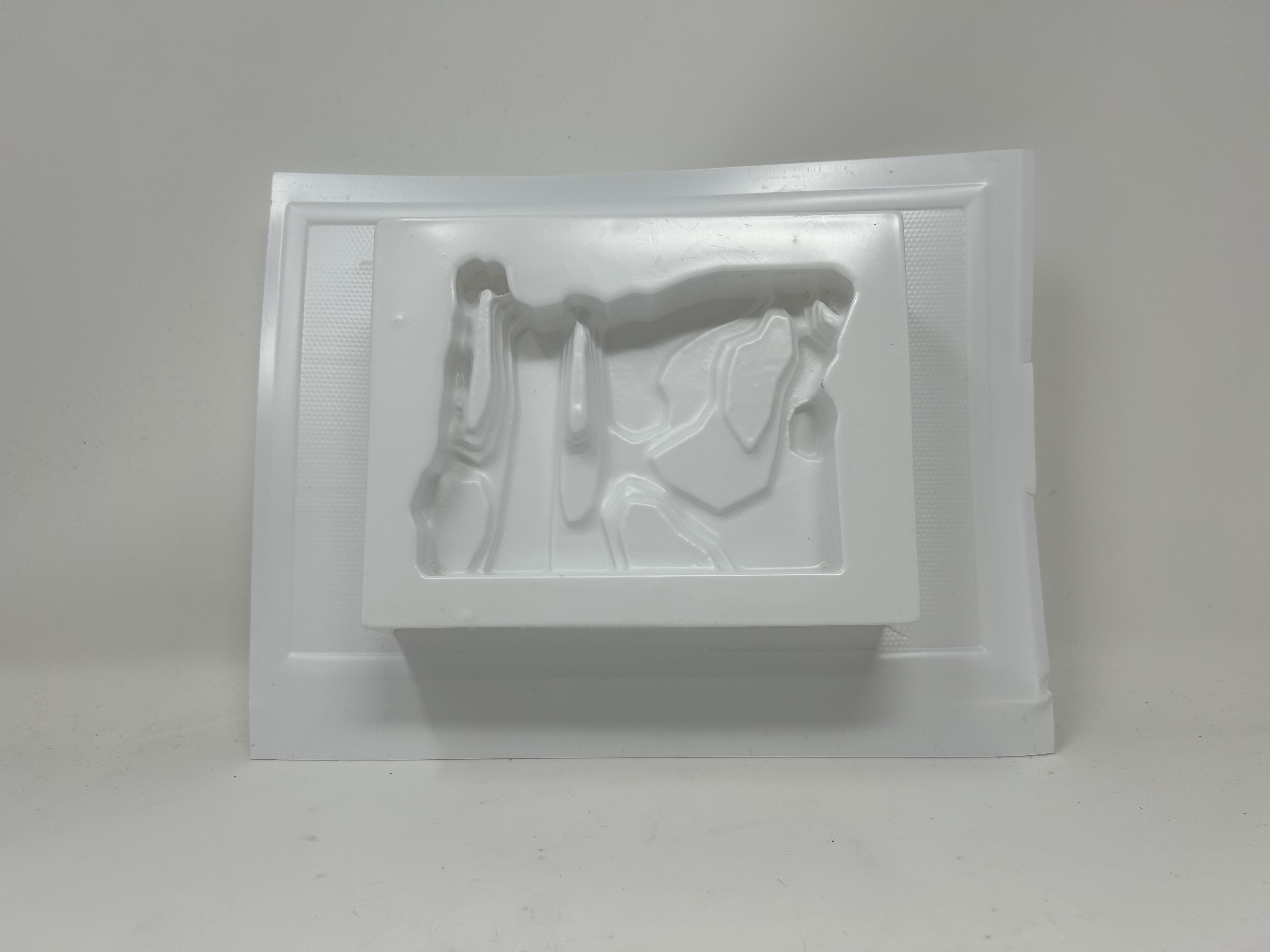
Using the milled wood block as a mold, I created a vacuum-formed replica using white plastic sheeting. The process successfully captured most of the topographic detail from the original, demonstrating the effectiveness of vacuum forming for replicating complex 3D surfaces. However, the tall profile of the block created challenges during demolding.
Front view of vacuum formed replica
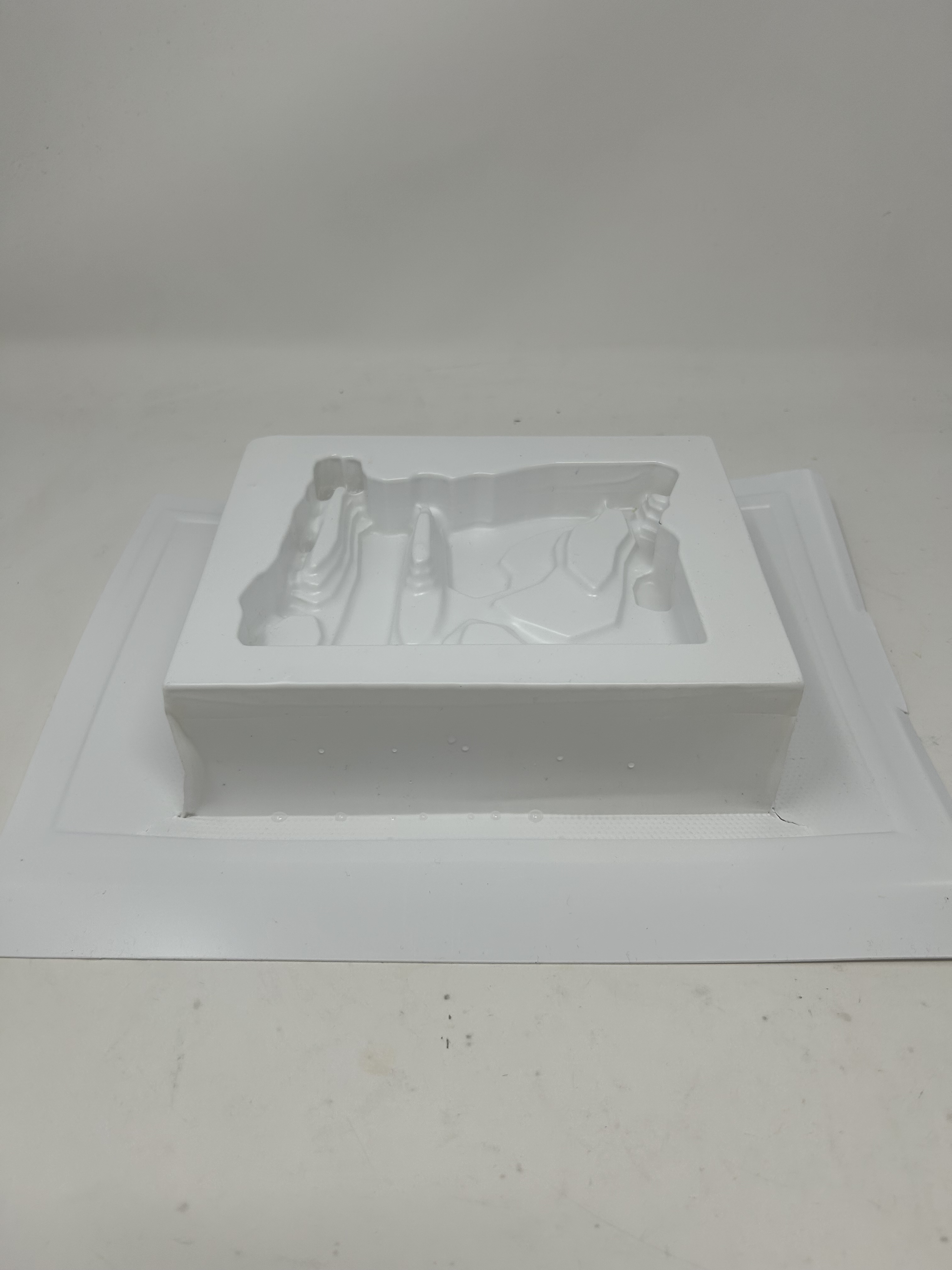
Angled view showing detail retention
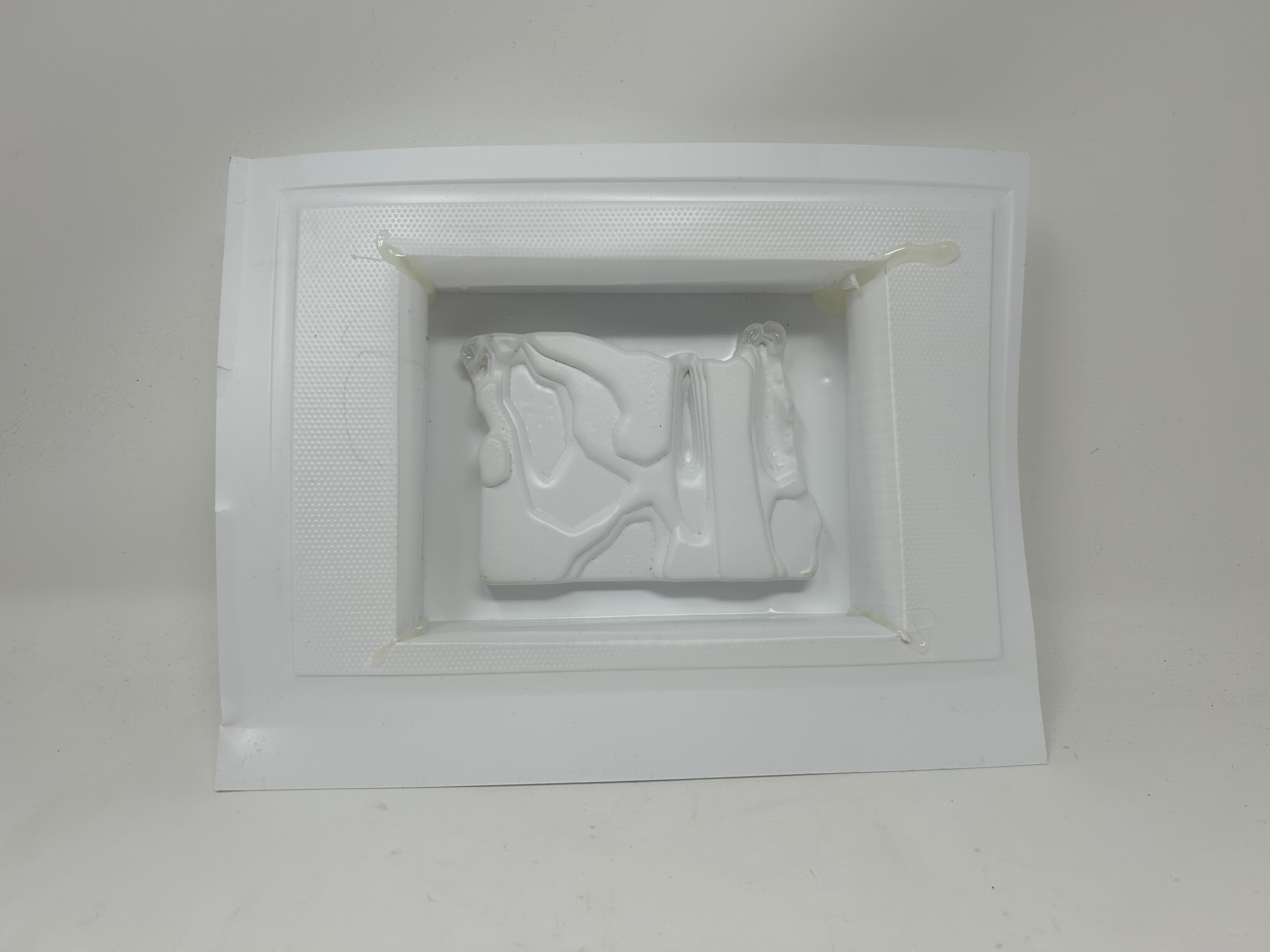
Back view of formed plastic
Vacuum Forming Process
Material Selection
Used thicker white plastic sheeting for the vacuum forming process. The material needed to be thick enough to capture detail but thin enough to form properly over the deep relief features.
Forming Process
Heated the plastic sheet until pliable, then used vacuum pressure to draw it tightly over the wooden mold. The process successfully replicated most of the topographic detail from the original carving.
Demolding Challenges
The tall profile of the mold (30mm depth) made it difficult to remove the formed plastic without damaging either the mold or the replica. The deep undercuts created by the topographic features increased the challenge of demolding.
Result: The vacuum forming process produced a successful replica that retained most of the detail from the CNC-milled original. The white plastic provides good contrast for viewing the topographic features, though the demolding process highlighted the design challenges of using tall molds with deep relief features in vacuum forming.
Lessons Learned & Reflections
✓What Worked Well
- •Fusion 360 CAM provided much better control and easier workflow than Aspire for this complex 3D carving
- •Laminating MDF blocks created a stable, uniform material perfect for deep relief milling
- •1/8" end mill balanced detail resolution with machining efficiency
- •Vacuum forming successfully captured most topographic details from the original
⚠Challenges & Solutions
- •CAM Software: Aspire proved too complex; switching to Fusion 360 CAM resolved workflow issues
- •Demolding: Tall mold profile made plastic removal difficult; future designs should consider draft angles
- •Stock Preparation: Proper glue-up and clamping of MDF layers was critical for preventing delamination during milling
→Future Improvements
- •Add draft angles to deep features to facilitate easier demolding in vacuum forming
- •Experiment with different plastic thicknesses to optimize detail capture vs. formability
- •Consider creating a two-part mold for easier demolding of complex geometries
- •Explore finishing techniques to enhance the appearance of both wood and plastic versions