Minimum Viable Product: Pan-Tilt Turret System
Building the mechanical foundation for the AI turret: complete CAD design, 3D printing, assembly, and servo control with oscilloscope analysis of PWM signals. Project updated to use laser pointer targeting for improved safety and continuous operation.
Project Overview
Minimum Viable Product
This week focused on tackling the most challenging aspects of my final project by developing both the hardware and software components independently. I completed the mechanical pan-tilt servo mechanism and integrated it with electronic control, while also building upon Week 6's ESP32-CAM human detection system. These parallel development tracks represent the core subsystems that will combine into the final AI-controlled turret.
Mechanical Design
Complete CAD model in Fusion 360 with integrated gear train, servo mounts, and lazy susan bearing for smooth 360° rotation. Fully assembled and tested hardware platform.
Electronic Control
ESP32 microcontroller with dual potentiometer inputs controlling two MG996R servos using C++ class structure and non-blocking code. Manual control validated before AI integration.
Vision System
ESP32-CAM with Edge Impulse-trained human detection model (from Week 6) provides the computer vision subsystem. Hardware and software developed independently, ready for integration.
MVP Development Strategy
By developing the mechanical platform and vision system as independent subsystems, I can test and refine each component before integration. The pan-tilt mechanism proves the hardware can handle servo loads and provide smooth motion, while the ESP32-CAM system (Week 6) demonstrates reliable human detection. The next phase will combine these systems, replacing manual potentiometer control with automated targeting based on camera input.
System Demonstration
Pan-tilt mechanism controlled by dual potentiometers - smooth servo motion across full range
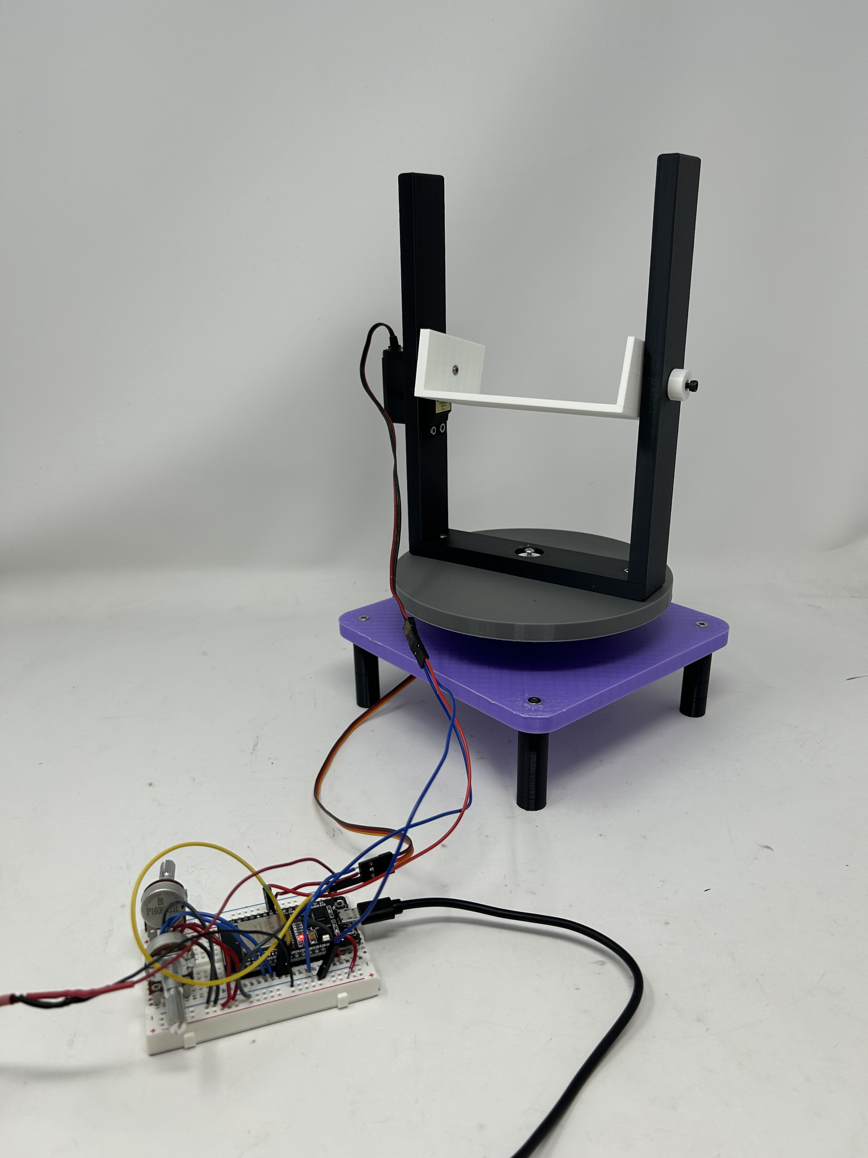
Complete MVP assembly with breadboard and power supply
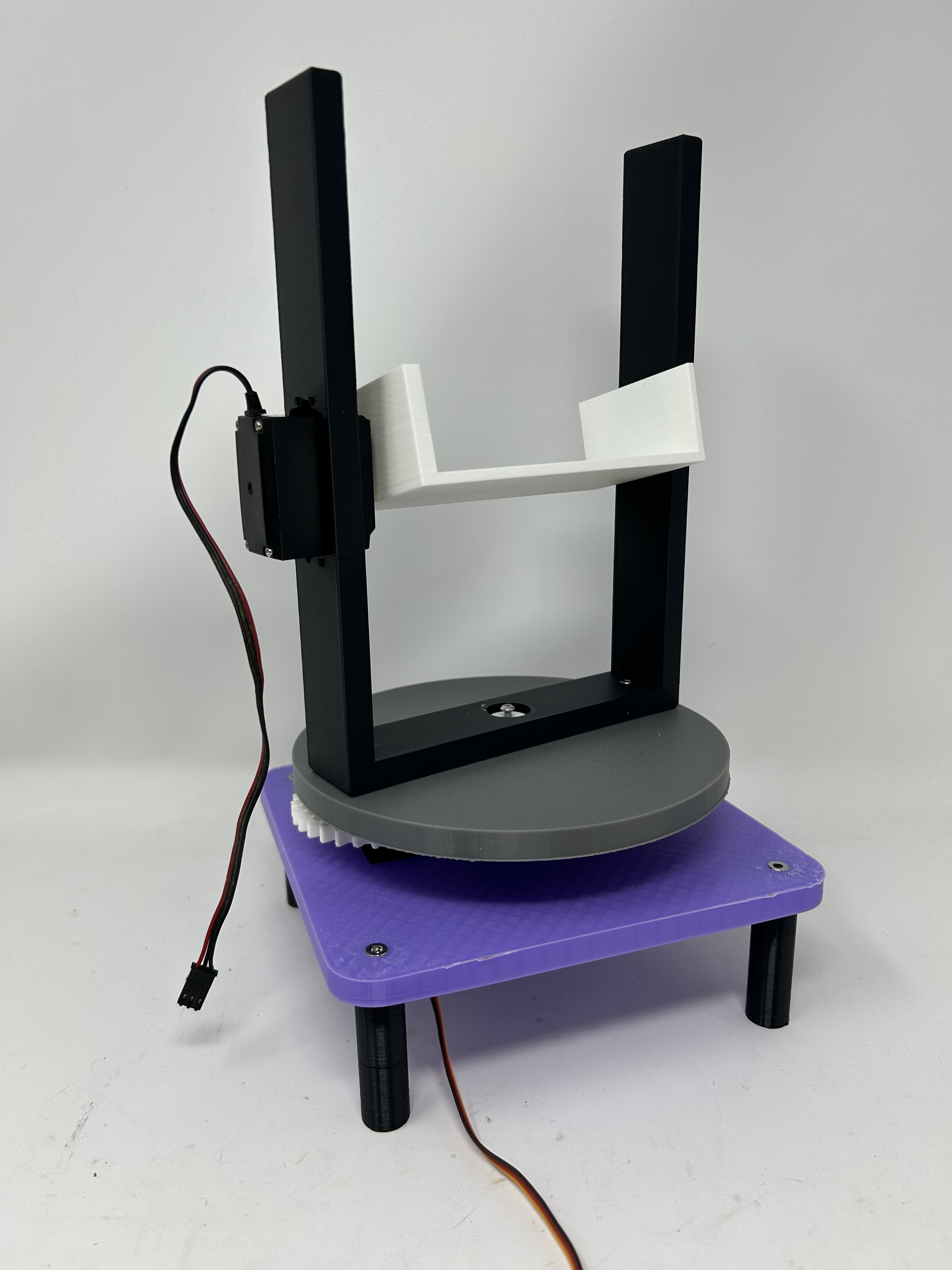
Pan-tilt mechanism with gear train and servo mounts
Mechanical Design & Fabrication
CAD Model
The pan-tilt platform was designed in Fusion 360 with careful consideration for servo mounting, gear ratios, and structural rigidity. The design incorporates a lazy susan bearing for the pan axis and a direct-drive servo for the tilt axis, providing smooth motion across the full range of movement.
Interactive 3D model of the pan-tilt turret platform
Download STL: The complete assembly is available as an STL file for 3D printing. Download AI Turret Platform (MVP).stl
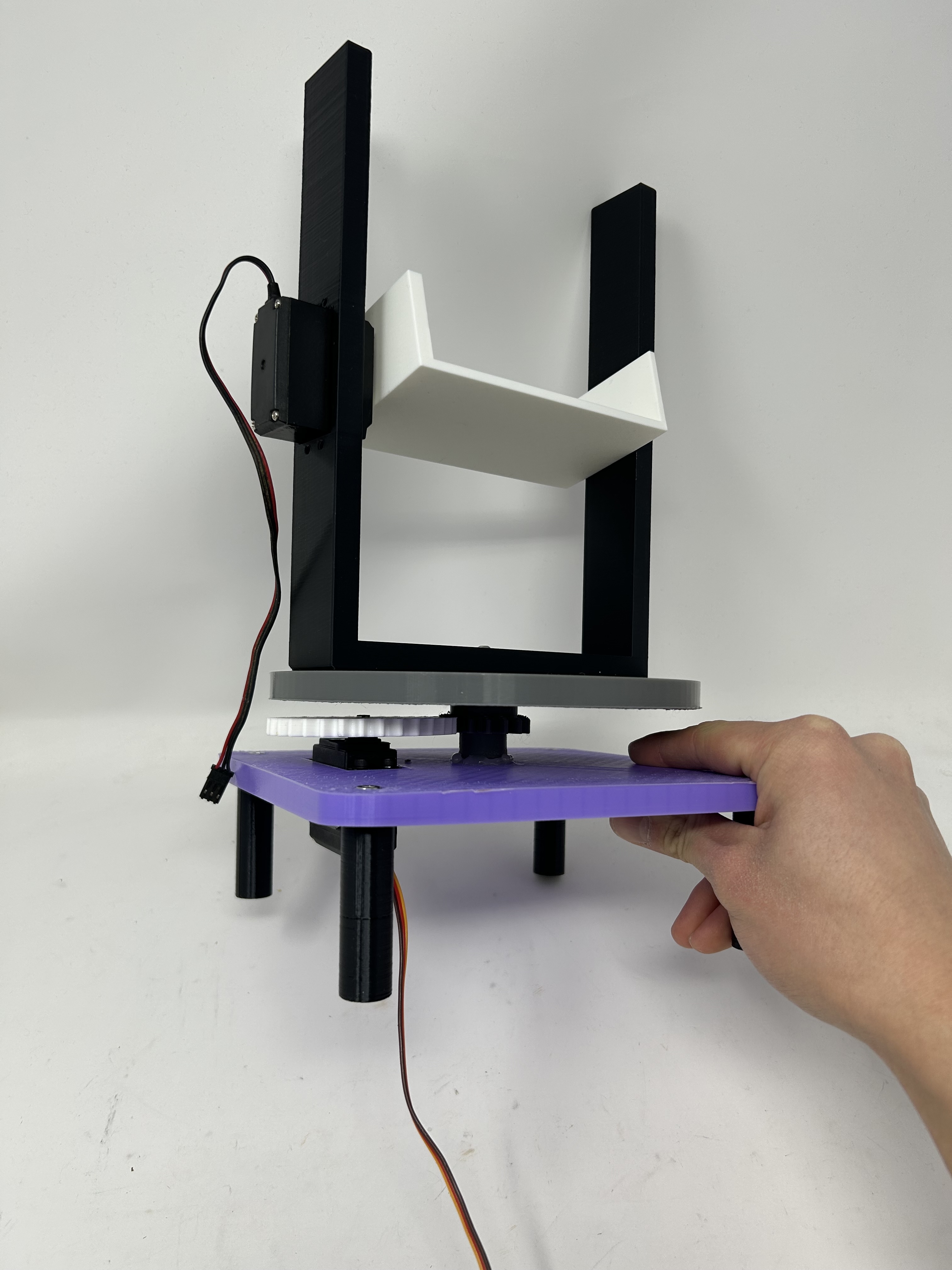
Gear train and servo mounting detail
Design Features
- Pan Axis: 360° rotation using lazy susan bearing with gear reduction for precise control
- Tilt Axis: Direct servo drive for vertical movement with integrated mounting bracket
- Servo Mounts: Custom-designed brackets to securely hold MG996R servos in position
- Material: PLA filament with 15% infill for strength while minimizing weight
Electronic Control System
Circuit Design
The control system uses an ESP32 microcontroller to read two potentiometers and control two MG996R servos. The servos are powered by a separate 5V AC-to-DC power supply to handle their current requirements, while the potentiometers run on the ESP32's 3.3V rail.
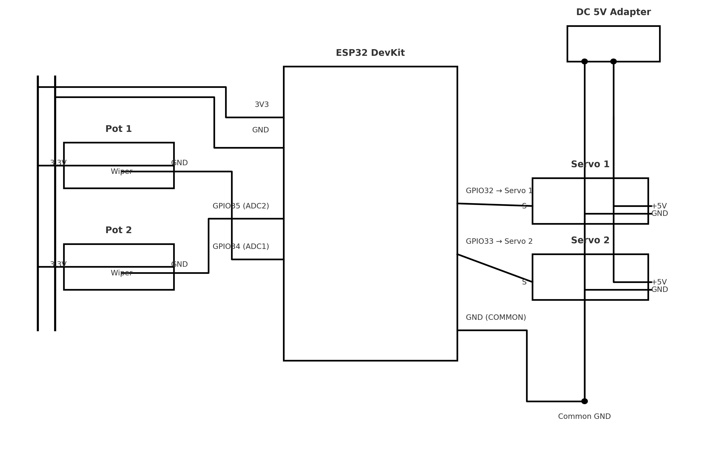
Circuit schematic showing connections and power distribution
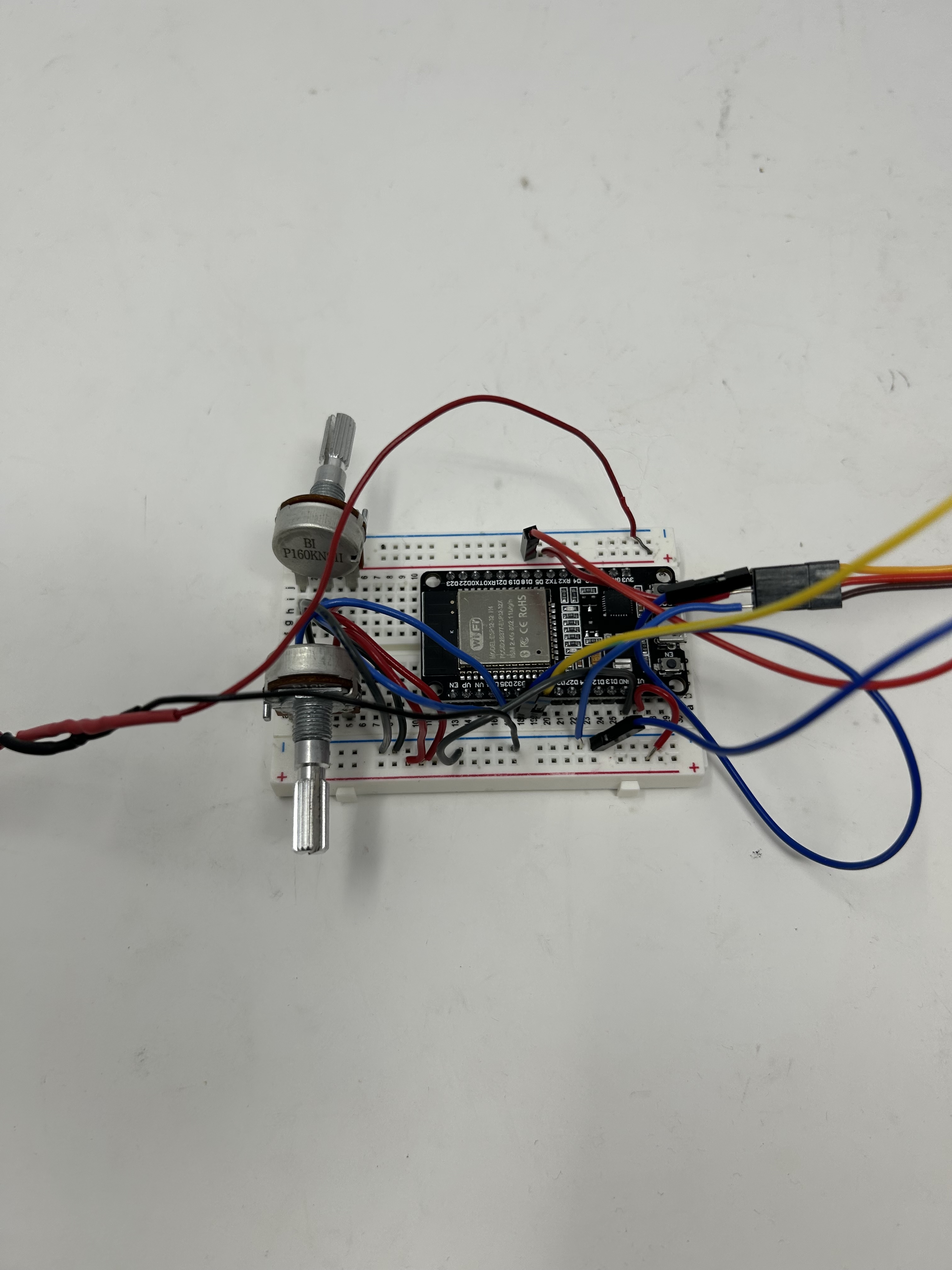
Physical breadboard implementation with components
Circuit Connections
Input Devices (Potentiometers)
- • Potentiometer 1: GPIO 34 (analog input)
- • Potentiometer 2: GPIO 35 (analog input)
- • Power: 3.3V from ESP32
- • Ground: Common ground with ESP32
Output Devices (Servos)
- • Servo 1 (Pan): GPIO 32 (PWM signal)
- • Servo 2 (Tilt): GPIO 33 (PWM signal)
- • Power: 5V external power supply
- • Ground: Common ground with ESP32
Power Design Note: The servos are powered from a separate 5V power supply on isolated breadboard rails to prevent voltage drops and noise from affecting the ESP32. Only the ground and signal wires connect between the ESP32 and servos, ensuring clean PWM signals while the servos draw their high current from the dedicated supply.
Code Implementation
The code uses C++ classes to encapsulate potentiometer reading and servo control functionality. The ServoWrapper and Potentiometer classes provide clean interfaces for hardware interaction, making the code modular and easy to extend. The loop continuously reads potentiometer values and maps them to servo positions without using delay().
#include <ESP32Servo.h>

class Potentiometer {
  int potPin;

  public:
    Potentiometer(int pin) {
      potPin = pin;
      pinMode(potPin, INPUT);
    }

    int read() {
      return analogRead(potPin);
    }
};

// Wrapper function to add more functionality later
class ServoWrapper {
  Servo servo;
  int servoPin;
  int startPos;

  public:
    ServoWrapper(int pin, int pos) {
      servoPin = pin;
      startPos = pos;
    }

    void attach() {
      servo.attach(servoPin);
      servo.write(startPos);
    }

    void move(int pos) {
      servo.write(pos);
    }
};

ServoWrapper s1(32, 0);
ServoWrapper s2(33, 0);
Potentiometer p1(34);
Potentiometer p2(35);

void setup() {
  Serial.begin(115200);
  delay(200);                         // let USB/driver settle
  Serial.println("\nBooting…");
  s1.attach();
  s2.attach();
}

void loop() {
  // put your main code here, to run repeatedly:
  int potVal1 = p1.read();
  int potVal2 = p2.read();

  Serial.printf("Pot 1: %d  Pot 2: %d\n", potVal1, potVal2);

  int servoVal1 = map(potVal1, 0, 4095, 0, 180);
  int servoVal2 = map(potVal2, 0, 4095, 0, 180);

  s1.move(servoVal1);
  s2.move(servoVal2);
}
Download: Get the complete Arduino sketch: assignment_7.ino
Code Highlights: The Potentiometer class encapsulates analog reading, while ServoWrapper provides a clean interface for servo control with initialization and movement methods. The map() function converts the ESP32's 12-bit ADC range (0-4095) to servo angles (0-180°), providing intuitive control through the potentiometers.
Oscilloscope Analysis: PWM Signals
Signal Characteristics
Using an oscilloscope, I measured the PWM signals sent from the ESP32 (pins 32 and 33) to the MG996R servos. The analysis revealed the timing characteristics of standard RC servo control signals and how pulse width modulation translates to servo position.
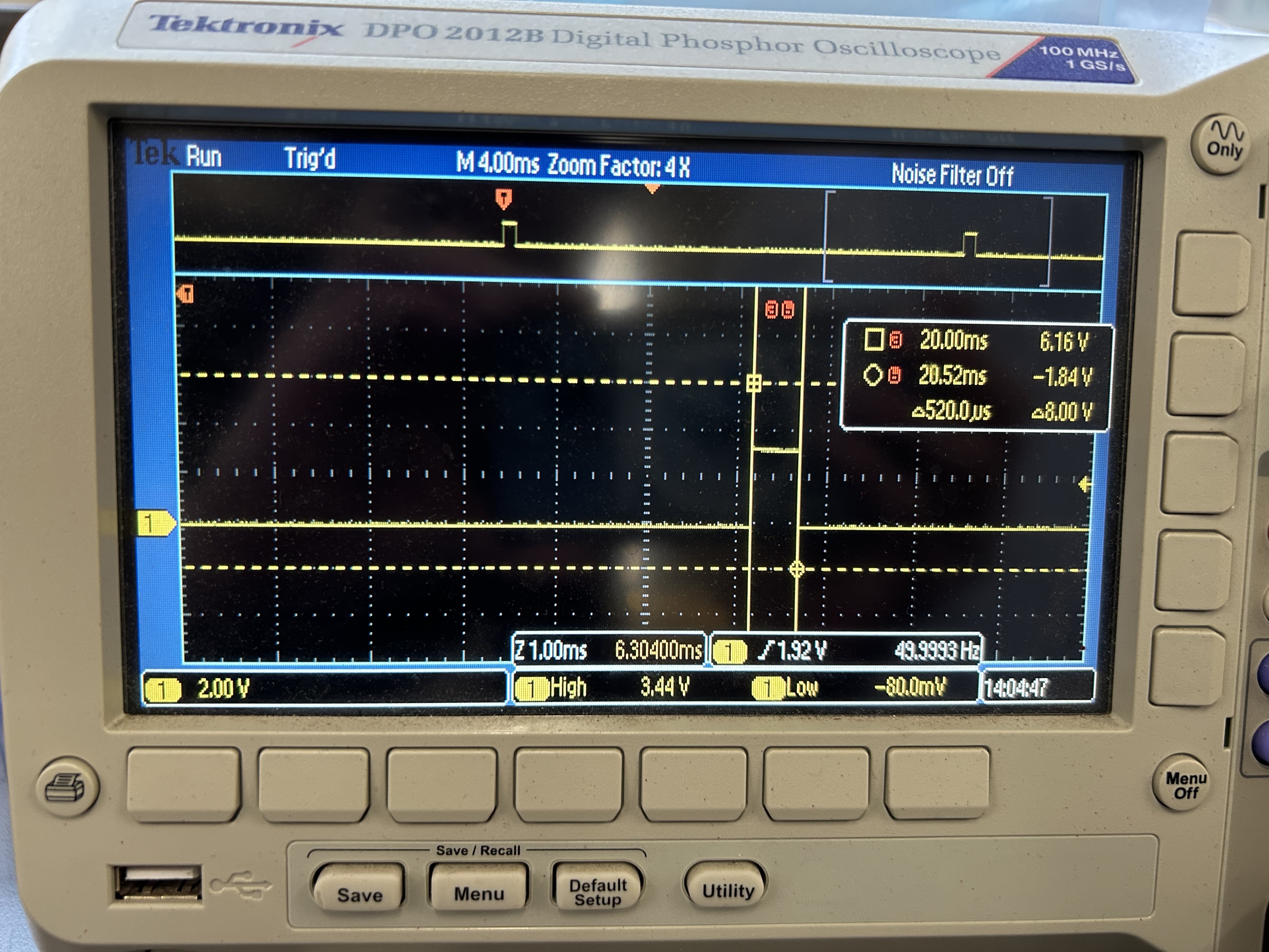
Minimum pulse: 520µs (0° position)
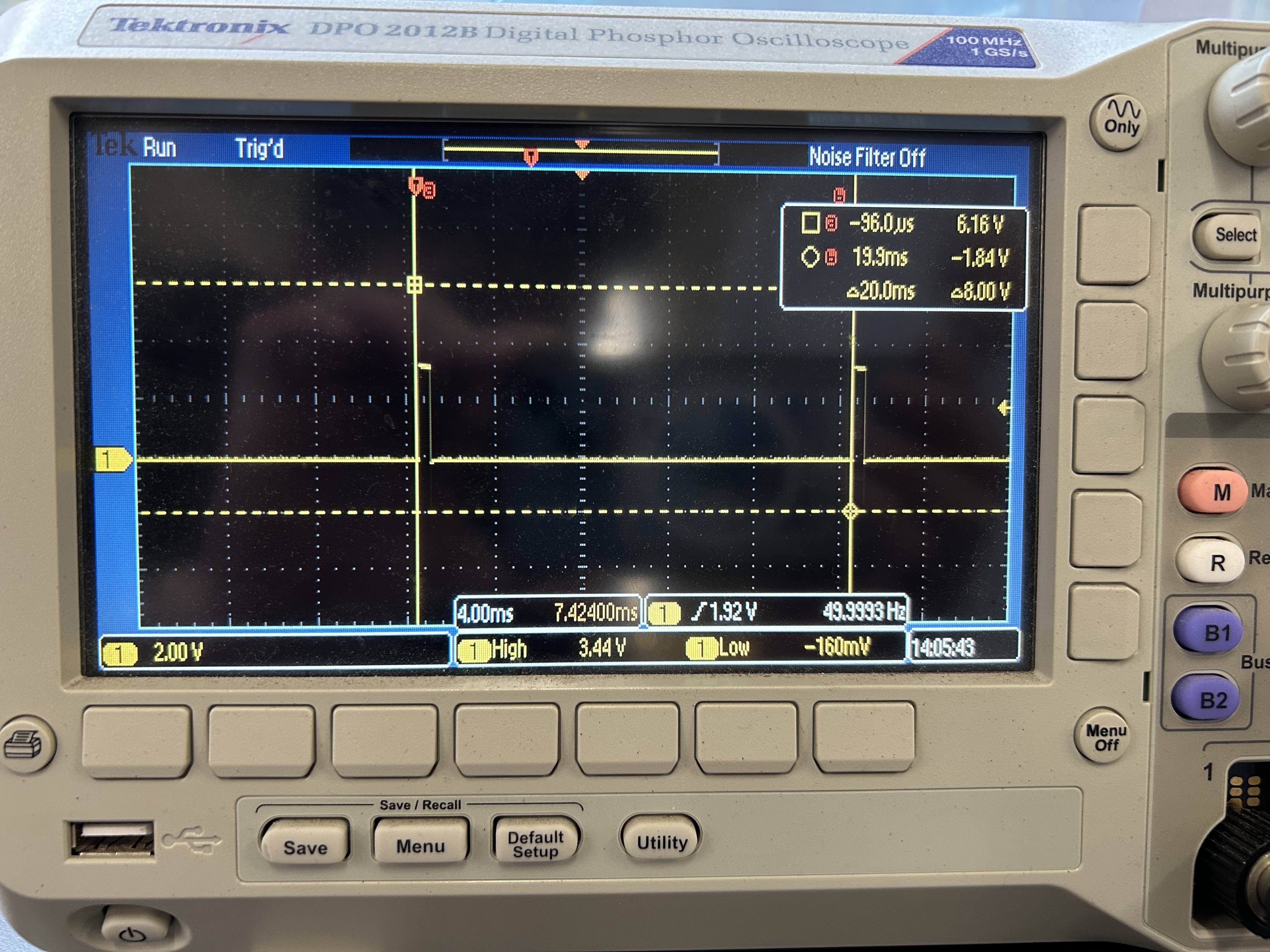
Signal period: 20ms between pulses (50Hz)
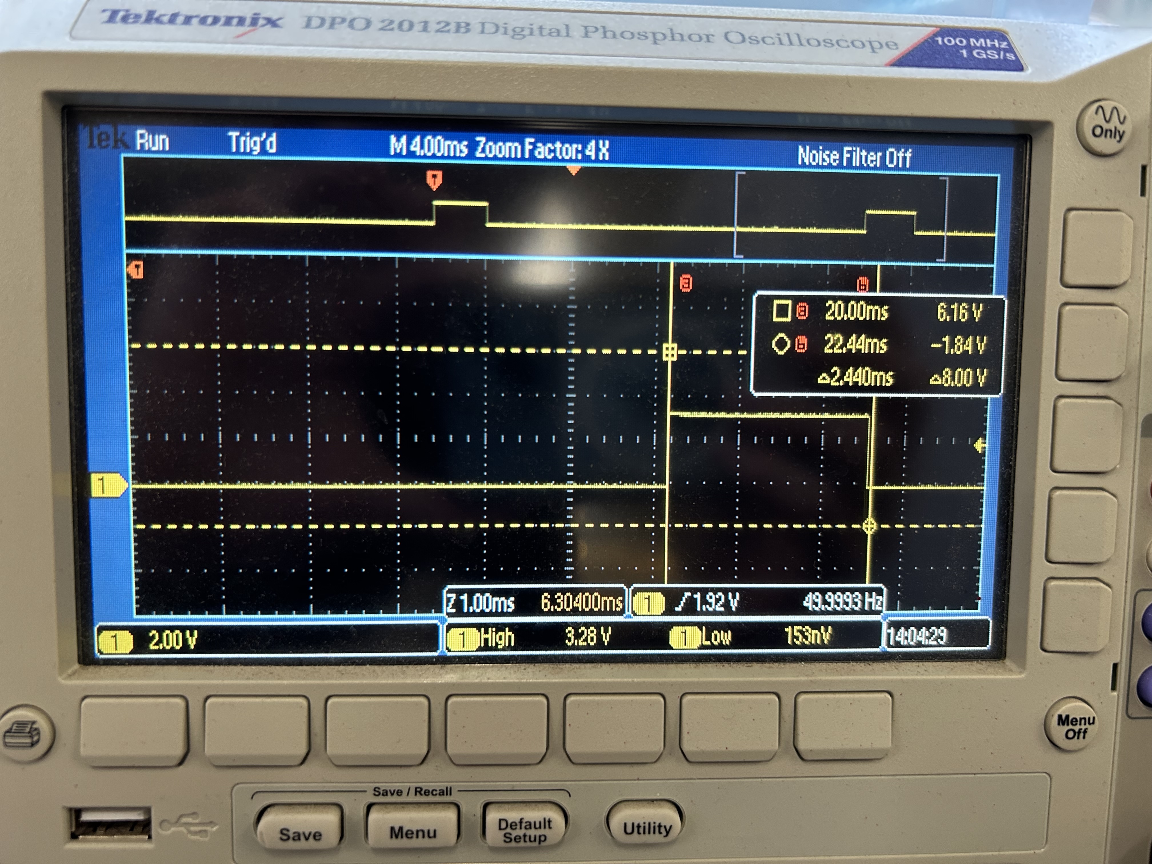
Maximum pulse: 2.44ms (180° position)
Measured Values
Signal Frequency
- • Period: 20 ms
- • Frequency: 50 Hz
- • Type: Fixed clock PWM signal
Pulse Width Range
- • Minimum: 520 µs (0°)
- • Maximum: 2.44 ms (180°)
- • Range: 1.92 ms total variation
Analysis & Findings
Fixed Clock Operation: The servo operates on a fixed 50 Hz clock, meaning it receives a control pulse every 20 milliseconds. This is standard for RC servos and ensures consistent, predictable behavior.
Pulse Width Modulation: The position is controlled by varying the pulse width within each 20ms period. A 520µs pulse commands 0°, while a 2.44ms pulse commands 180°. The servo's internal control circuitry decodes this pulse width and drives the motor to the corresponding position.
Standard Servo Protocol: These measurements align with standard RC servo specifications, which typically use 1-2ms pulse widths for the full 0-180° range. The MG996R extends this slightly (0.52-2.44ms) for its full mechanical range.
ESP32 PWM Generation: The ESP32Servo library generates these precise timing signals using the microcontroller's hardware PWM channels, ensuring accurate and jitter-free control even while the main loop executes other code.
Reflection
This week's MVP development proved that the mechanical foundation of my turret project is sound. Successfully designing, printing, and assembling the pan-tilt mechanism validated my CAD skills and demonstrated that the structure can handle the servo loads. The smooth operation across the full range of motion gives me confidence that this platform will work well for the final AI-controlled system.
The oscilloscope analysis was particularly enlightening—seeing the actual PWM signals and understanding how microsecond-level timing translates to precise mechanical positioning deepened my appreciation for servo control. The 50 Hz update rate means the system can respond to targeting commands 50 times per second, which should be more than adequate for tracking moving targets. Next steps include integrating the ESP32-CAM vision system and implementing the automatic targeting algorithms.