Electronic Input Devices & Sensors
Building custom capacitive sensors and integrating computer vision with ESP32-CAM for real-time human detection.
Project Overview
This Week's Focus
This week explored electronic input devices through two main projects: building a custom capacitive weight sensor from scratch and implementing computer vision on an ESP32-CAM for real-time human detection. Both projects required careful sensor design, calibration, and integration of output devices for feedback.
Capacitive Sensing
Designed and built a spring-based weight sensor using capacitance principles. The sensor measures weight by detecting changes in capacitance as copper plates compress, demonstrating how physical phenomena can be converted to electrical signals.
Computer Vision
Programmed an ESP32-CAM to detect humans in real-time using a machine learning model trained with Edge Impulse. The system processes camera frames, runs inference, and controls an LED based on detection results—all on a microcontroller.
Capacitive Weight Sensor
Design Concept
I designed and built a spring-based weight sensor using capacitive sensing principles. The sensor consists of two copper plates separated by air inside a black enclosure. As weight is applied to the top of the box, it compresses the spring, decreasing the distance between the copper plates and increasing the capacitance. The ESP32 microcontroller measures these capacitance changes to determine the applied weight.
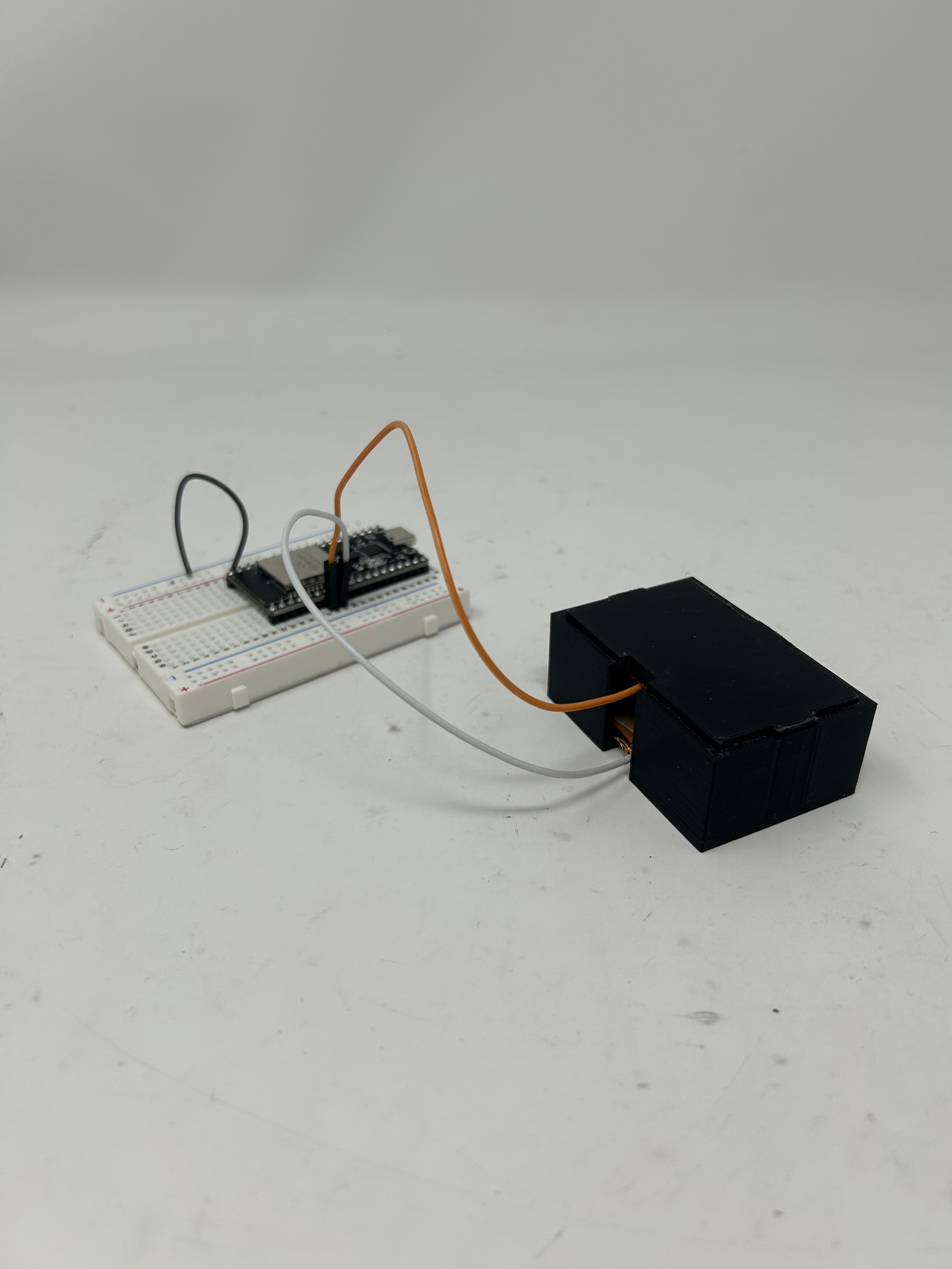
Complete sensor assembly with ESP32 connection
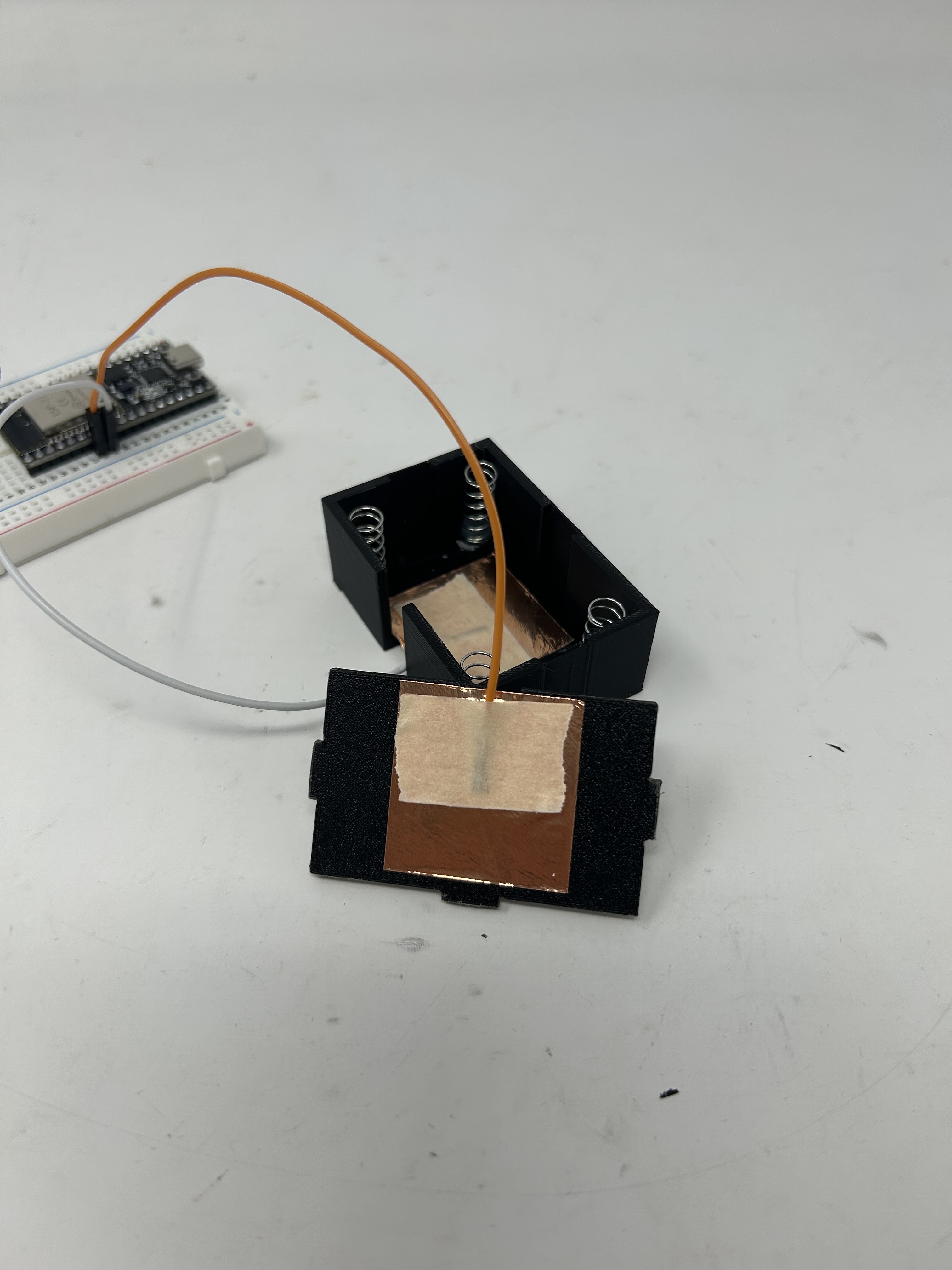
Internal copper plates with air gap capacitor design
Demonstration of capacitive sensor responding to applied weight
3D Printed Enclosure
The sensor housing was designed in Fusion 360 and 3D printed to create a rigid enclosure that maintains consistent spacing between the copper plates while allowing controlled compression of the internal spring mechanism.
Interactive 3D model of the capacitive sensor enclosure
How It Works
Capacitance Formula: C = ε₀ × εᵣ × A / d
Where d is the distance between plates - as weight compresses the spring, d decreases and capacitance C increases.
Measurement Method: The ESP32 charges the capacitor through a transmit pin and measures the voltage difference using an analog pin. The time-based sampling approach (using micros() instead of delay()) allows for non-blocking operation.
Circuit Schematic
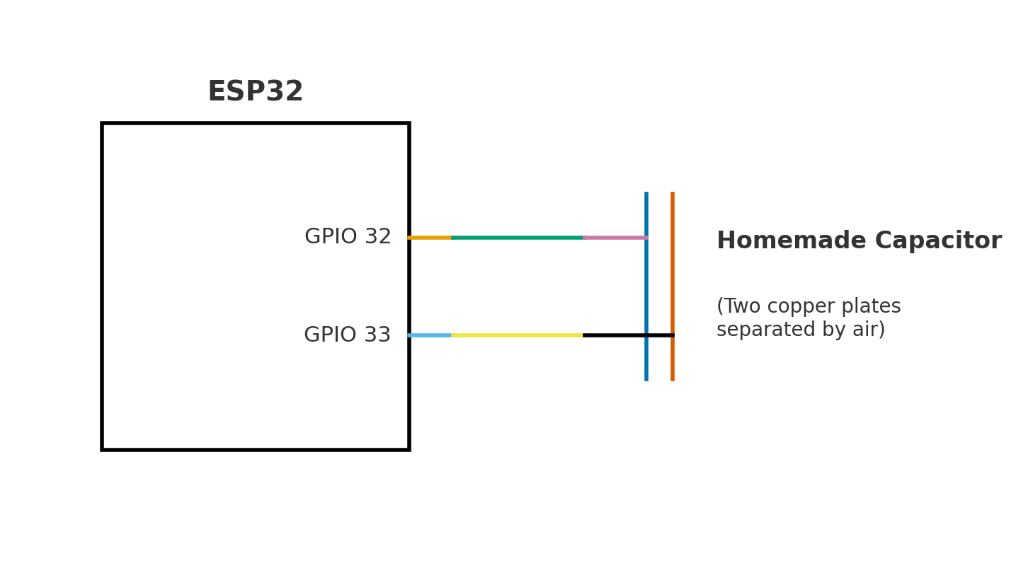
ESP32 capacitive sensing circuit - TX pin (GPIO 33) charges the capacitor, analog pin (GPIO 32) reads voltage
Code Implementation
The code uses a C++ class structure to implement non-blocking capacitive sensing. The CapacitorSensor class manages state internally and uses micros() for precise timing without blocking other operations.
long result;   //variable for the result of the tx_rx measurement.

class CapacitorSensor {
  public:
    CapacitorSensor(int t_pin, int a_pin, int n_samples, unsigned long wait_us = 100)
      : tx_pin(t_pin), analog_pin(a_pin), N_samples(n_samples), wait_us(wait_us) {}

    void begin() {
      pinMode(tx_pin, OUTPUT);
      digitalWrite(tx_pin, LOW);
      resetRun();
      done = false;
      have_last_value = false;
    }

    bool update() {
      if (done) return true;  // hold result until read()

      unsigned long now = micros();

      switch (phase) {
        case 0: // start a new sample
          digitalWrite(tx_pin, HIGH);
          read_high = analogRead(analog_pin);
          t_mark = now;
          phase = 1;
          break;

        case 1: // wait for wait_us and take second reading
          if ((unsigned long)(now - t_mark) >= wait_us) {
            digitalWrite(tx_pin, LOW);
            int read_low = analogRead(analog_pin);
            sum += (long)(read_high - read_low);
            samples_done++;
            phase = 0;
            if (samples_done >= N_samples) {
              last_value = sum;
              done = true;
              have_last_value = true;
              resetRun(); // prep for next cycle
            }
          }
          break;
      }
      return done;
    }

    // get finished result and clear "done" flag
    long read() {
      done = false;
      return last_value;
    }

    bool available() const { return have_last_value && done; }

  private:
    int tx_pin;
    int analog_pin;
    int N_samples;
    unsigned long wait_us;

    // state
    int phase = 0;  // 0 = start sample, 1 = waiting
    unsigned long t_mark = 0; // time marker from micros()
    int read_high = 0;
    long sum = 0;
    int samples_done = 0;

    // output
    long last_value = 0;
    bool done = false;
    bool have_last_value = false;

    void resetRun() {
      phase = 0;
      t_mark = 0;
      sum = 0;
      samples_done = 0;
    }
};

CapacitorSensor cs(33, 32, 100, 100);

void setup() {
  Serial.begin(9600);
  cs.begin();
}

void loop() {
  if (cs.update()) {
    long v = cs.read();
    Serial.println(v);
  }
}
Key Features: Non-blocking state machine design using micros() for timing, C++ class encapsulation for clean code structure, averaging over 100 samples for noise reduction, and proper resource management with state flags.
Sensor Calibration
I calibrated the sensor by measuring known weights and recording the corresponding capacitance readings. The data reveals a strong linear relationship between applied weight and sensor output.
.png)
Calibration Data
| Weight (g) | Capacitor Reading | Reading/Weight Ratio |
|---|---|---|
| 1,110 | 84,000 | 75.7 |
| 2,175 | 91,000 | 41.8 |
| 3,285 | 94,000 | 28.6 |
| 4,105 | 97,500 | 23.8 |
Analysis
The relationship between weight and capacitance reading is approximately linear, as evidenced by the calibration curve. The sensor shows good sensitivity across the tested range (1.1 kg to 4.1 kg), with a total range of approximately 13,500 units. This linear response makes it straightforward to convert raw sensor readings to weight values using a simple calibration equation.
The slight variations in the reading/weight ratio suggest some non-linearity at the extremes, likely due to the spring's compression characteristics and the inverse relationship between plate distance and capacitance (C ∝ 1/d). However, for practical applications, a linear approximation provides sufficient accuracy.
ESP32-CAM Human Detection
Computer Vision on the Edge
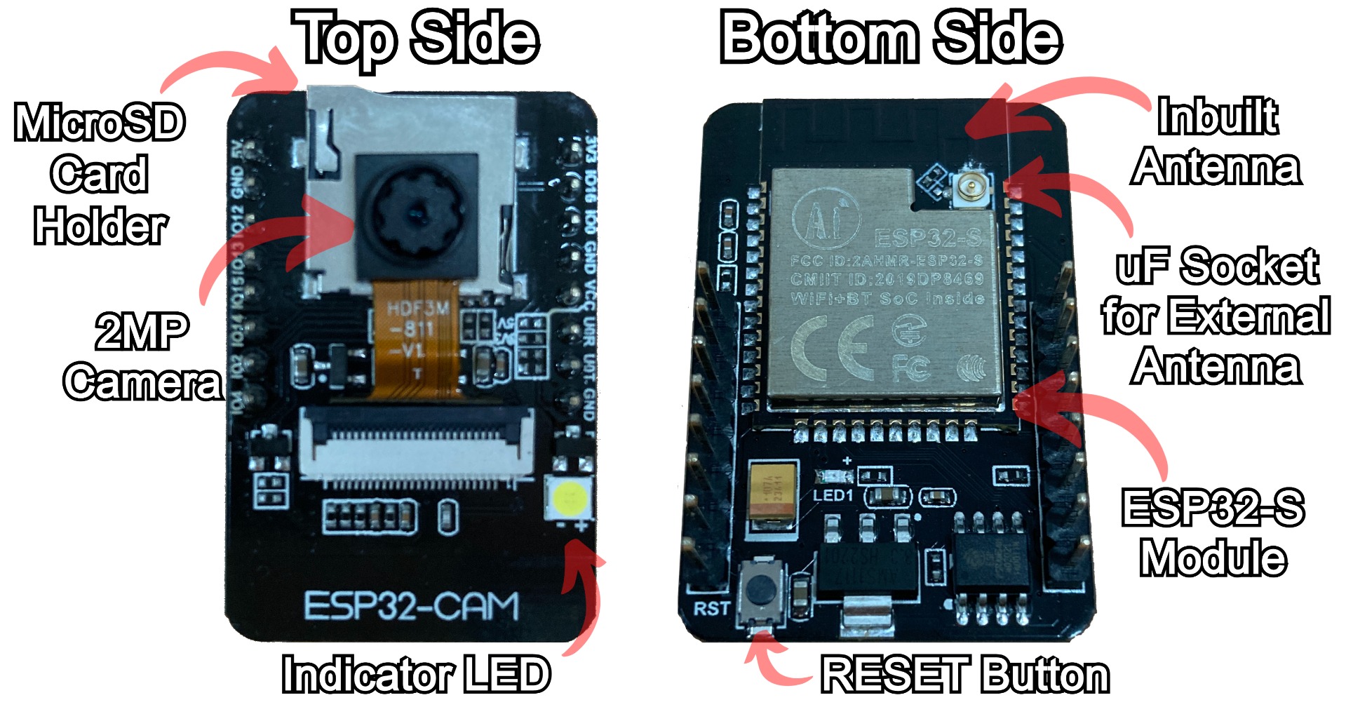
I programmed an ESP32-CAM AI Thinker module to perform real-time human detection using a machine learning model trained with Edge Impulse. The system captures images, runs object detection inference, and controls an LED output based on whether a person is detected.
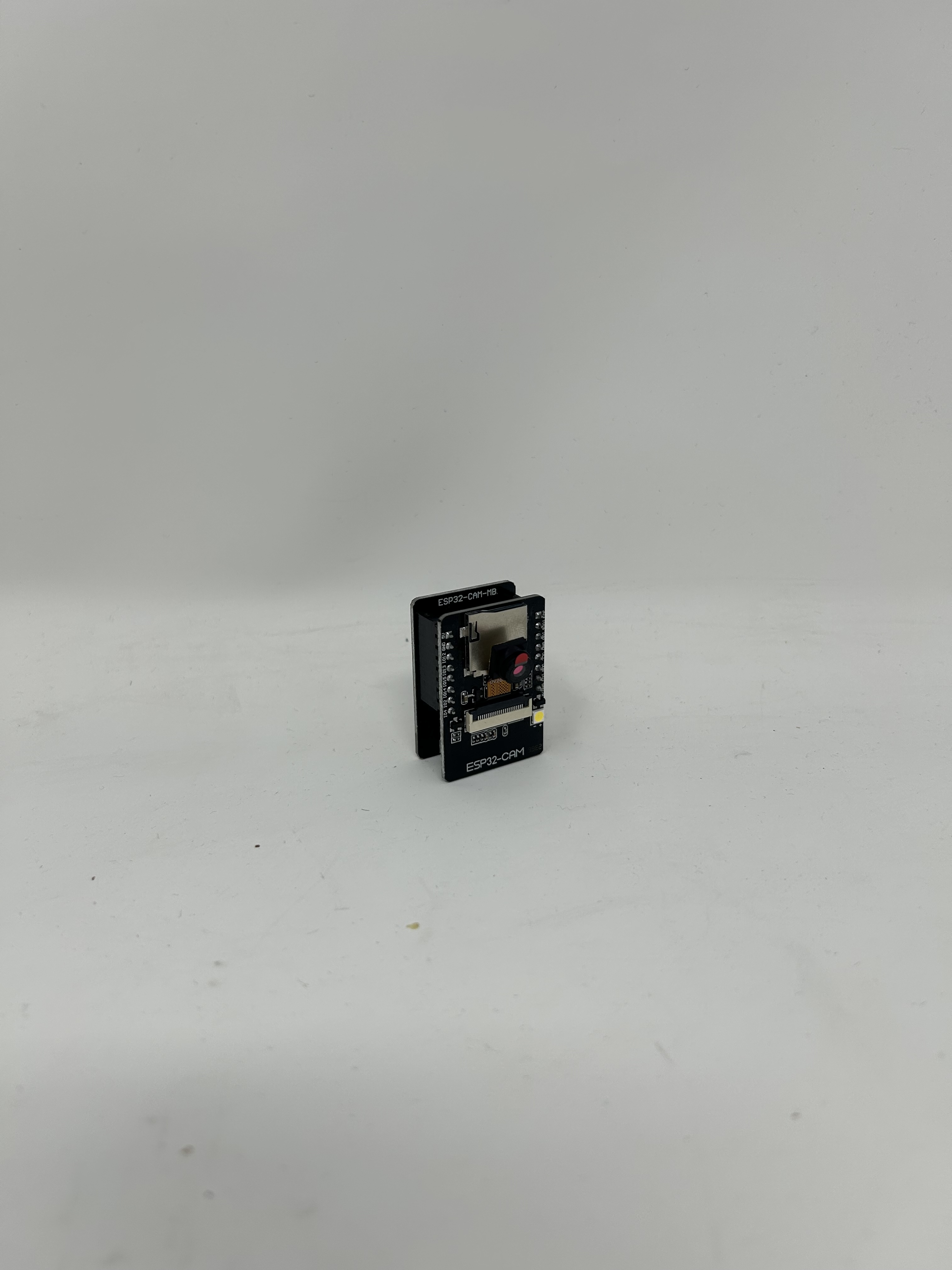
ESP32-CAM AI Thinker module with camera and built-in flash LED
Real-time human detection - LED turns on when a person is detected in frame
Model Details
- • Architecture: FOMO MobileNetV2
- • Input Size: 224x224 pixels
- • Training Data: Kaggle People Detection Dataset
- • Inference Time: ~4 seconds per frame
Performance Metrics
- • Training Accuracy: 82%
- • Test Accuracy: 40%
- • Detection Threshold: 60% confidence
- • LED Control: Built-in flash (GPIO 4)
Model Training Note: Accuracy for both training and test sets increased significantly when image resolution was increased from 96×96 to 224×224 pixels. At the lower resolution, accuracy was approximately half of the final values, demonstrating the importance of sufficient input detail for person detection.
Published Model: View the trained model and explore the training process at Edge Impulse Studio
Circuit Schematic
ESP32-CAM AI Thinker pinout and connections - LED flash on GPIO 4 controlled by detection results
Code Implementation
The code integrates Edge Impulse's inference library with the ESP32 camera driver. It continuously captures frames, runs object detection, and controls the LED based on detection confidence. When a person is detected with ≥60% confidence, the built-in flash LED turns on.
/* Edge Impulse Arduino examples
 * Copyright (c) 2022 EdgeImpulse Inc.
 *
 * Permission is hereby granted, free of charge, to any person obtaining a copy
 * of this software and associated documentation files (the "Software"), to deal
 * in the Software without restriction, including without limitation the rights
 * to use, copy, modify, merge, publish, distribute, sublicense, and/or sell
 * copies of the Software, and to permit persons to whom the Software is
 * furnished to do so, subject to the following conditions:
 *
 * The above copyright notice and this permission notice shall be included in
 * all copies or substantial portions of the Software.
 *
 * THE SOFTWARE IS PROVIDED "AS IS", WITHOUT WARRANTY OF ANY KIND, EXPRESS OR
 * IMPLIED, INCLUDING BUT NOT LIMITED TO THE WARRANTIES OF MERCHANTABILITY,
 * FITNESS FOR A PARTICULAR PURPOSE AND NONINFRINGEMENT. IN NO EVENT SHALL THE
 * AUTHORS OR COPYRIGHT HOLDERS BE LIABLE FOR ANY CLAIM, DAMAGES OR OTHER
 * LIABILITY, WHETHER IN AN ACTION OF CONTRACT, TORT OR OTHERWISE, ARISING FROM,
 * OUT OF OR IN CONNECTION WITH THE SOFTWARE OR THE USE OR OTHER DEALINGS IN THE
 * SOFTWARE.
 */

// These sketches are tested with 2.0.4 ESP32 Arduino Core
// https://github.com/espressif/arduino-esp32/releases/tag/2.0.4

/* Includes ---------------------------------------------------------------- */
#include <ai-sentry_inferencing.h>
#include "edge-impulse-sdk/dsp/image/image.hpp"

#include "esp_camera.h"

// Select camera model - find more camera models in camera_pins.h file here
// https://github.com/espressif/arduino-esp32/blob/master/libraries/ESP32/examples/Camera/CameraWebServer/camera_pins.h

//#define CAMERA_MODEL_ESP_EYE // Has PSRAM
#define CAMERA_MODEL_AI_THINKER // Has PSRAM

#if defined(CAMERA_MODEL_ESP_EYE)
#define PWDN_GPIO_NUM    -1
#define RESET_GPIO_NUM   -1
#define XCLK_GPIO_NUM    4
#define SIOD_GPIO_NUM    18
#define SIOC_GPIO_NUM    23

#define Y9_GPIO_NUM      36
#define Y8_GPIO_NUM      37
#define Y7_GPIO_NUM      38
#define Y6_GPIO_NUM      39
#define Y5_GPIO_NUM      35
#define Y4_GPIO_NUM      14
#define Y3_GPIO_NUM      13
#define Y2_GPIO_NUM      34
#define VSYNC_GPIO_NUM   5
#define HREF_GPIO_NUM    27
#define PCLK_GPIO_NUM    25

#elif defined(CAMERA_MODEL_AI_THINKER)
#define PWDN_GPIO_NUM     32
#define RESET_GPIO_NUM    -1
#define XCLK_GPIO_NUM      0
#define SIOD_GPIO_NUM     26
#define SIOC_GPIO_NUM     27

#define Y9_GPIO_NUM       35
#define Y8_GPIO_NUM       34
#define Y7_GPIO_NUM       39
#define Y6_GPIO_NUM       36
#define Y5_GPIO_NUM       21
#define Y4_GPIO_NUM       19
#define Y3_GPIO_NUM       18
#define Y2_GPIO_NUM        5
#define VSYNC_GPIO_NUM    25
#define HREF_GPIO_NUM     23
#define PCLK_GPIO_NUM     22
#define LED_FLASH_PIN      4

#else
#error "Camera model not selected"
#endif

/* Constant defines -------------------------------------------------------- */
#define EI_CAMERA_RAW_FRAME_BUFFER_COLS           320
#define EI_CAMERA_RAW_FRAME_BUFFER_ROWS           240
#define EI_CAMERA_FRAME_BYTE_SIZE                 3

/* Private variables ------------------------------------------------------- */
static bool debug_nn = false; // Set this to true to see e.g. features generated from the raw signal
static bool is_initialised = false;
uint8_t *snapshot_buf; //points to the output of the capture

static camera_config_t camera_config = {
    .pin_pwdn = PWDN_GPIO_NUM,
    .pin_reset = RESET_GPIO_NUM,
    .pin_xclk = XCLK_GPIO_NUM,
    .pin_sscb_sda = SIOD_GPIO_NUM,
    .pin_sscb_scl = SIOC_GPIO_NUM,

    .pin_d7 = Y9_GPIO_NUM,
    .pin_d6 = Y8_GPIO_NUM,
    .pin_d5 = Y7_GPIO_NUM,
    .pin_d4 = Y6_GPIO_NUM,
    .pin_d3 = Y5_GPIO_NUM,
    .pin_d2 = Y4_GPIO_NUM,
    .pin_d1 = Y3_GPIO_NUM,
    .pin_d0 = Y2_GPIO_NUM,
    .pin_vsync = VSYNC_GPIO_NUM,
    .pin_href = HREF_GPIO_NUM,
    .pin_pclk = PCLK_GPIO_NUM,

    //XCLK 20MHz or 10MHz for OV2640 double FPS (Experimental)
    .xclk_freq_hz = 20000000,
    .ledc_timer = LEDC_TIMER_0,
    .ledc_channel = LEDC_CHANNEL_0,

    .pixel_format = PIXFORMAT_JPEG, //YUV422,GRAYSCALE,RGB565,JPEG
    .frame_size = FRAMESIZE_QVGA,    //QQVGA-UXGA Do not use sizes above QVGA when not JPEG

    .jpeg_quality = 12, //0-63 lower number means higher quality
    .fb_count = 1,       //if more than one, i2s runs in continuous mode. Use only with JPEG
    .fb_location = CAMERA_FB_IN_PSRAM,
    .grab_mode = CAMERA_GRAB_WHEN_EMPTY,
};

/* Function definitions ------------------------------------------------------- */
bool ei_camera_init(void);
void ei_camera_deinit(void);
bool ei_camera_capture(uint32_t img_width, uint32_t img_height, uint8_t *out_buf) ;

/**
* @brief      Arduino setup function
*/
void setup()
{
    // put your setup code here, to run once:
    Serial.begin(115200);
    pinMode(LED_FLASH_PIN, OUTPUT);
    //comment out the below line to start inference immediately after upload
    while (!Serial);
    Serial.println("Edge Impulse Inferencing Demo");
    if (ei_camera_init() == false) {
        ei_printf("Failed to initialize Camera!\r\n");
    }
    else {
        ei_printf("Camera initialized\r\n");
    }

    ei_printf("\nStarting continious inference in 2 seconds...\n");
    ei_sleep(2000);
}

/**
* @brief      Get data and run inferencing
*
* @param[in]  debug  Get debug info if true
*/
void loop()
{

    // instead of wait_ms, we'll wait on the signal, this allows threads to cancel us...
    if (ei_sleep(5) != EI_IMPULSE_OK) {
        return;
    }

    snapshot_buf = (uint8_t*)malloc(EI_CAMERA_RAW_FRAME_BUFFER_COLS * EI_CAMERA_RAW_FRAME_BUFFER_ROWS * EI_CAMERA_FRAME_BYTE_SIZE);

    // check if allocation was successful
    if(snapshot_buf == nullptr) {
        ei_printf("ERR: Failed to allocate snapshot buffer!\n");
        return;
    }

    ei::signal_t signal;
    signal.total_length = EI_CLASSIFIER_INPUT_WIDTH * EI_CLASSIFIER_INPUT_HEIGHT;
    signal.get_data = &ei_camera_get_data;

    if (ei_camera_capture((size_t)EI_CLASSIFIER_INPUT_WIDTH, (size_t)EI_CLASSIFIER_INPUT_HEIGHT, snapshot_buf) == false) {
        ei_printf("Failed to capture image\r\n");
        free(snapshot_buf);
        return;
    }

    // Run the classifier
    ei_impulse_result_t result = { 0 };

    EI_IMPULSE_ERROR err = run_classifier(&signal, &result, debug_nn);
    if (err != EI_IMPULSE_OK) {
        ei_printf("ERR: Failed to run classifier (%d)\n", err);
        return;
    }

    // print the predictions
    ei_printf("Predictions (DSP: %d ms., Classification: %d ms., Anomaly: %d ms.): \n",
                result.timing.dsp, result.timing.classification, result.timing.anomaly);

#if EI_CLASSIFIER_OBJECT_DETECTION == 1
    ei_printf("Object detection bounding boxes:\r\n");
    bool person_found = false;

    for (uint32_t i = 0; i < result.bounding_boxes_count; i++) {
        ei_impulse_result_bounding_box_t bb = result.bounding_boxes[i];
        if (bb.value == 0) {
            continue;
        }

        // Checking if we detected a person with a high enough confidence
        if (strcmp(bb.label, "person") == 0 && bb.value >= 0.6f) {
            person_found = true;
        }

        ei_printf("  %s (%f) [ x: %u, y: %u, width: %u, height: %u ]\r\n",
                bb.label,
                bb.value,
                bb.x,
                bb.y,
                bb.width,
                bb.height);
    }

    // Set LED once per frame
    digitalWrite(LED_FLASH_PIN, person_found ? HIGH : LOW);

    // Print the prediction results (classification)
#else
    ei_printf("Predictions:\r\n");
    for (uint16_t i = 0; i < EI_CLASSIFIER_LABEL_COUNT; i++) {
        ei_printf("  %s: ", ei_classifier_inferencing_categories[i]);
        ei_printf("%.5f\r\n", result.classification[i].value);
    }
#endif

    // Print anomaly result (if it exists)
#if EI_CLASSIFIER_HAS_ANOMALY
    ei_printf("Anomaly prediction: %.3f\r\n", result.anomaly);
#endif

#if EI_CLASSIFIER_HAS_VISUAL_ANOMALY
    ei_printf("Visual anomalies:\r\n");
    for (uint32_t i = 0; i < result.visual_ad_count; i++) {
        ei_impulse_result_bounding_box_t bb = result.visual_ad_grid_cells[i];
        if (bb.value == 0) {
            continue;
        }
        ei_printf("  %s (%f) [ x: %u, y: %u, width: %u, height: %u ]\r\n",
                bb.label,
                bb.value,
                bb.x,
                bb.y,
                bb.width,
                bb.height);
    }
#endif


    free(snapshot_buf);

}

/**
 * @brief   Setup image sensor & start streaming
 *
 * @retval  false if initialisation failed
 */
bool ei_camera_init(void) {

    if (is_initialised) return true;

#if defined(CAMERA_MODEL_ESP_EYE)
  pinMode(13, INPUT_PULLUP);
  pinMode(14, INPUT_PULLUP);
#endif

    //initialize the camera
    esp_err_t err = esp_camera_init(&camera_config);
    if (err != ESP_OK) {
      Serial.printf("Camera init failed with error 0x%x\n", err);
      return false;
    }

    sensor_t * s = esp_camera_sensor_get();
    // initial sensors are flipped vertically and colors are a bit saturated
    if (s->id.PID == OV3660_PID) {
      s->set_vflip(s, 1); // flip it back
      s->set_brightness(s, 1); // up the brightness just a bit
      s->set_saturation(s, 0); // lower the saturation
    }

#if defined(CAMERA_MODEL_M5STACK_WIDE)
    s->set_vflip(s, 1);
    s->set_hmirror(s, 1);
#elif defined(CAMERA_MODEL_ESP_EYE)
    s->set_vflip(s, 1);
    s->set_hmirror(s, 1);
    s->set_awb_gain(s, 1);
#endif

    is_initialised = true;
    return true;
}

/**
 * @brief      Stop streaming of sensor data
 */
void ei_camera_deinit(void) {

    //deinitialize the camera
    esp_err_t err = esp_camera_deinit();

    if (err != ESP_OK)
    {
        ei_printf("Camera deinit failed\n");
        return;
    }

    is_initialised = false;
    return;
}


/**
 * @brief      Capture, rescale and crop image
 *
 * @param[in]  img_width     width of output image
 * @param[in]  img_height    height of output image
 * @param[in]  out_buf       pointer to store output image, NULL may be used
 *                           if ei_camera_frame_buffer is to be used for capture and resize/cropping.
 *
 * @retval     false if not initialised, image captured, rescaled or cropped failed
 *
 */
bool ei_camera_capture(uint32_t img_width, uint32_t img_height, uint8_t *out_buf) {
    bool do_resize = false;

    if (!is_initialised) {
        ei_printf("ERR: Camera is not initialized\r\n");
        return false;
    }

    camera_fb_t *fb = esp_camera_fb_get();

    if (!fb) {
        ei_printf("Camera capture failed\n");
        return false;
    }

   bool converted = fmt2rgb888(fb->buf, fb->len, PIXFORMAT_JPEG, snapshot_buf);

   esp_camera_fb_return(fb);

   if(!converted){
       ei_printf("Conversion failed\n");
       return false;
   }

    if ((img_width != EI_CAMERA_RAW_FRAME_BUFFER_COLS)
        || (img_height != EI_CAMERA_RAW_FRAME_BUFFER_ROWS)) {
        do_resize = true;
    }

    if (do_resize) {
        ei::image::processing::crop_and_interpolate_rgb888(
        out_buf,
        EI_CAMERA_RAW_FRAME_BUFFER_COLS,
        EI_CAMERA_RAW_FRAME_BUFFER_ROWS,
        out_buf,
        img_width,
        img_height);
    }


    return true;
}

static int ei_camera_get_data(size_t offset, size_t length, float *out_ptr)
{
    // we already have a RGB888 buffer, so recalculate offset into pixel index
    size_t pixel_ix = offset * 3;
    size_t pixels_left = length;
    size_t out_ptr_ix = 0;

    while (pixels_left != 0) {
        // Swap BGR to RGB here
        // due to https://github.com/espressif/esp32-camera/issues/379
        out_ptr[out_ptr_ix] = (snapshot_buf[pixel_ix + 2] << 16) + (snapshot_buf[pixel_ix + 1] << 8) + snapshot_buf[pixel_ix];

        // go to the next pixel
        out_ptr_ix++;
        pixel_ix+=3;
        pixels_left--;
    }
    // and done!
    return 0;
}

#if !defined(EI_CLASSIFIER_SENSOR) || EI_CLASSIFIER_SENSOR != EI_CLASSIFIER_SENSOR_CAMERA
#error "Invalid model for current sensor"
#endif
LED Control Logic (Lines 197-220): The code checks each detected bounding box for the label "person" with confidence ≥60%. If found, person_found is set to true, which drives the LED_FLASH_PIN (GPIO 4) HIGH. The LED state is updated once per inference cycle.
Performance & Observations
Strengths
- • Successfully detects humans in real-time
- • Runs entirely on-device (no cloud required)
- • Immediate LED feedback for detection
- • Low power consumption
- • Compact form factor
Limitations
- • ~4 second inference time is slow for real-time tracking
- • Limited 224×224 input resolution
- • Test accuracy (40%) lower than desired
- • Single-class detection only
- • Performance varies with lighting conditions
Future Improvements: The system could be optimized by using quantized models, implementing frame skipping, or upgrading to a more powerful microcontroller. The test accuracy gap suggests potential overfitting that could be addressed with data augmentation and regularization techniques.
Files for CNC Milling
For the CNC milling week, I prepared CAD models to be machined from stronger materials. These designs will replace 3D printed parts with CNC-milled components for improved durability and precision in the final turret system.
Turret Pan-Tilt Platform
This is the turret platform originally designed in Week 5. I plan to CNC mill this from aluminum or hardwood for stronger, more rigid parts compared to 3D printing. The improved material will handle the servo torque and mechanical stress better during rapid targeting movements.
Interactive 3D model of the turret pan-tilt base (to be CNC milled)
Oregon State Imprint
A decorative Oregon state outline designed for CNC routing or engraving. This piece demonstrates 2D toolpath generation and will be machined from wood or acrylic sheet material.
Interactive 3D model of the Oregon state imprint design
Manufacturing Plan: The turret platform will be CNC milled for structural components requiring high strength and precision. The Oregon imprint will demonstrate 2D routing techniques and artistic CNC applications.
Reflection
This week demonstrated the power of embedded sensing and edge AI. Building a custom capacitive sensor from scratch taught me about the physics of capacitance and the importance of proper calibration. The linear relationship I observed validated the theoretical model and showed how even simple physics principles can create reliable sensors.
The ESP32-CAM human detection project revealed both the potential and limitations of running machine learning on resource-constrained devices. While the 4-second inference time is slow, the ability to perform computer vision entirely on a $12 microcontroller is remarkable. The experience with Edge Impulse streamlined the model training process and highlighted how accessible embedded ML has become. These skills will be directly applicable to the turret project's targeting system.