3D Printed Pan-Tilt Base for AI Turret
Designing and 3D printing the foundational base component for my final project AI turret, featuring integrated gear system and servo mounting for precise pan control.
Design Overview
Pan-Tilt Turret Base
This week marks a significant milestone in my final project: creating the first physical component of the AI-controlled turret system. The pan-tilt base serves as the foundation for the entire turret, providing stable mounting and precise rotational control through an integrated gear system driven by a high-torque servo.
Design Features
- • Integrated gear system for pan rotation
- • Servo drives the larger gear for greater range of rotation
- • Servo mounting cavity with precise tolerances
- • Stable base with four mounting legs
- • Optimized for 3D printing without supports
Technical Specifications
- • Material: PLA filament
- • Layer height: 0.2mm
- • Printer: Prusa i3 MK3S
- • Assembly: M3 and M4 screws
Interactive 3D Model
Fusion 360 CAD Model
Explore the complete 3D model of the turret base. The design features a gear-driven pan mechanism where the servo drives the larger gear for greater range of rotation of the platform, a servo mounting cavity, and four stable legs. This interactive viewer allows you to rotate, zoom, and examine the intricate details of the component before fabrication.
3D Printed Results
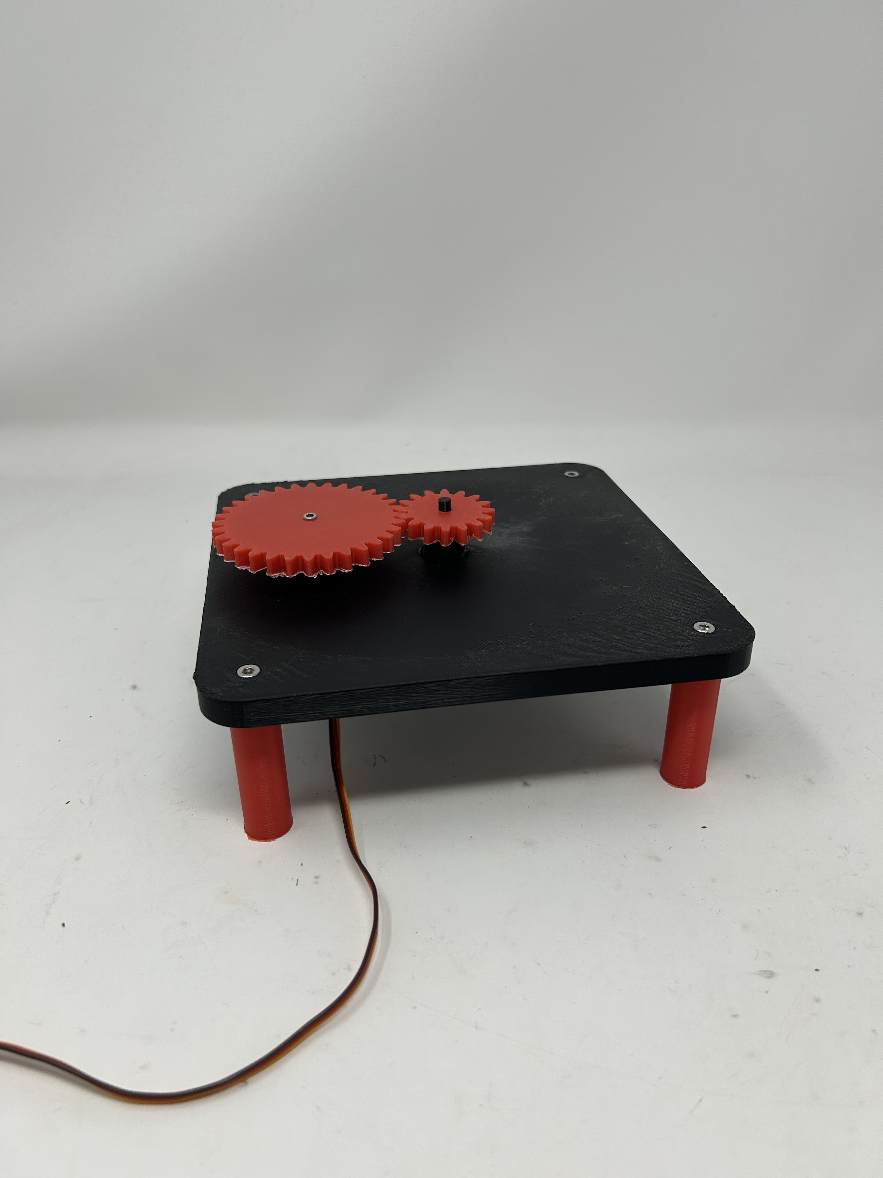
Top View - Gear System
The top view showcases the larger circular gear integrated into the base design. The gear teeth are precisely modeled to mesh with the smaller gear, providing greater range of rotation and enabling smooth 360-degree pan rotation for the turret platform.
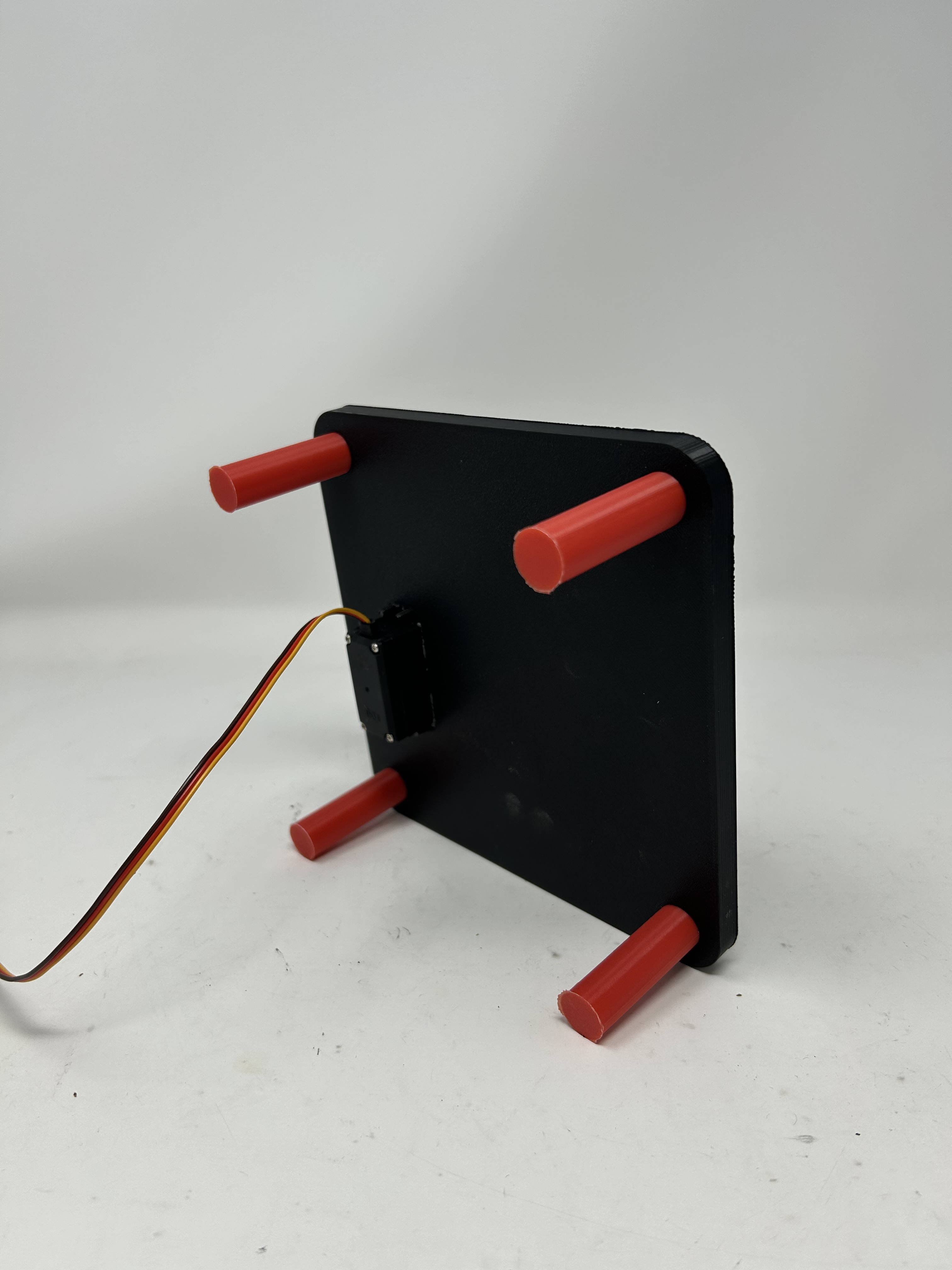
Angle View - Structural Design
An angled perspective reveals the four-leg support structure and the central servo mounting cavity. The legs provide stable support while the elevated design allows for full range of motion without obstruction.
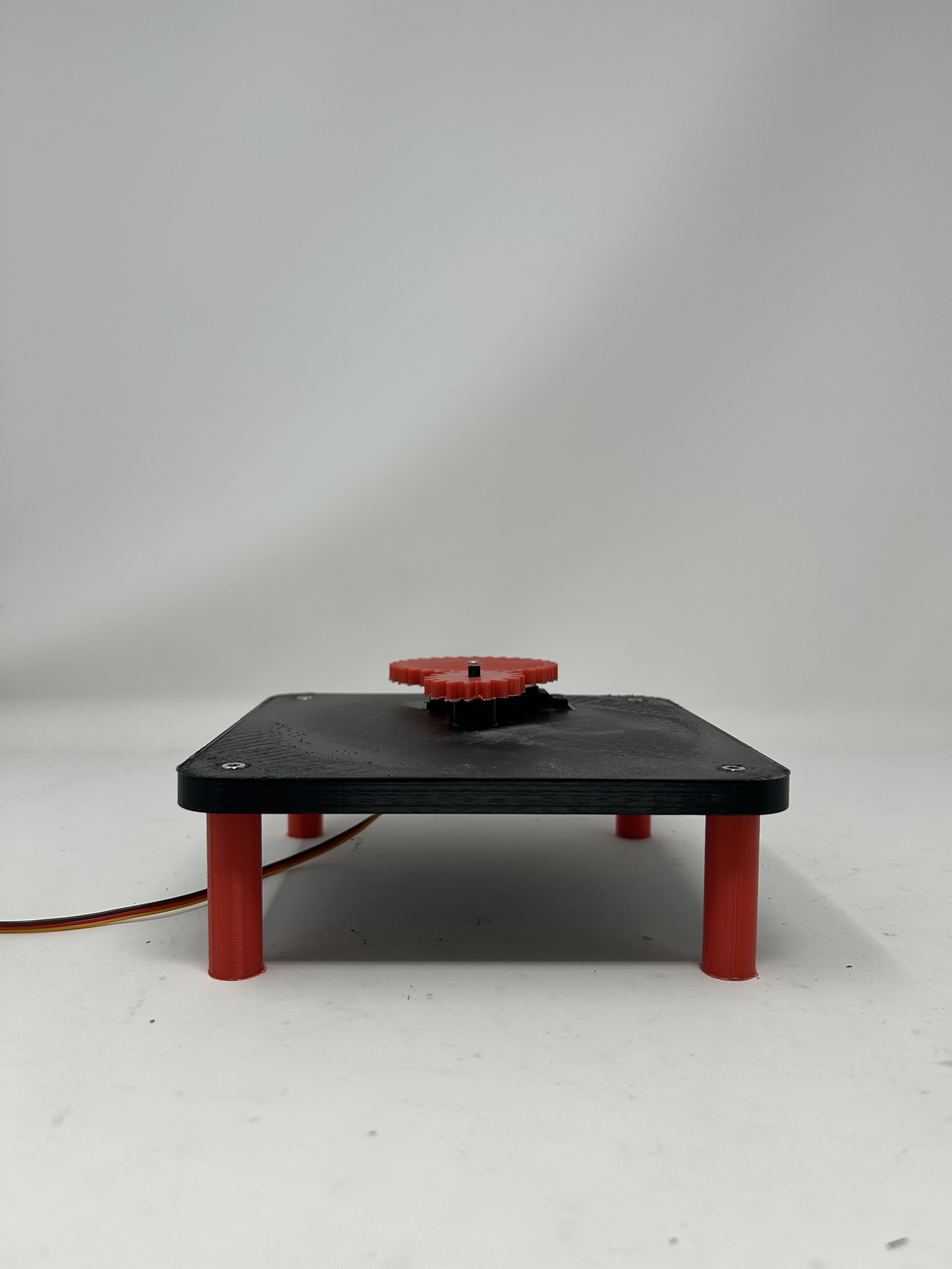
Complete Assembly View
The fully assembled base with the Miuzei MG996R servo motor installed and secured with M3 and M4 screws. The servo drives the larger gear to provide greater range of rotation and precise rotational control for the pan axis of the turret platform.
Print Settings & Assembly
3D Printing Parameters
- Material: PLA filament for dimensional accuracy and ease of printing
- Layer Height: 0.2mm for balance between quality and print time
- Printer: Prusa i3 MK3S with reliable bed adhesion
- Infill: Standard settings optimized for structural strength
Hardware Components
- Servo Motor: Miuzei MG996R high-torque digital servo
- Leg Mounting: M4 screws for secure leg attachment
- Gear Assembly: M3 screws for gear mechanism
- Servo Specs: 11kg·cm torque, 4.8-6.6V operating voltage
Challenges & Solutions
Dimensional Accuracy Issues
The primary challenge encountered was that the printed dimensions were smaller than the CAD model specifications. This is a common issue with 3D printing due to material shrinkage during cooling and printer calibration variations.
The servo mounting cavity printed too tight, preventing the MG996R servo from sliding into the base smoothly, which would have caused stress on both the print and the servo housing.
Post-Processing Solution
The solution involved careful filing of the servo mounting cavity to achieve the proper fit. Using hand files, material was gradually removed until the servo could slide smoothly into position while maintaining a snug, secure fit.
- • Filed interior walls of servo cavity
- • Test-fit servo repeatedly during filing process
- • Achieved smooth sliding fit without play
- • Maintained structural integrity of mount
Design Iteration Lessons
This challenge reinforced an important lesson in digital fabrication: always account for material properties and manufacturing tolerances in your CAD designs. For future iterations, I will add 0.2-0.3mm clearance to critical fit dimensions in the CAD model to account for PLA shrinkage and printer variations, reducing the need for post-processing. This experience demonstrates that physical prototyping is essential - even with precise CAD models, real-world manufacturing requires iteration and adjustment.
Download 3D Model Files
Access the complete set of files for this project, including the parametric CAD model, printable STL file, and pre-sliced G-code ready for Prusa printers.
3D Scanning with Revopoint
Scanning Setup & Process
Using the Revopoint 3D scanner with Revoscan software, I captured detailed 3D scans of two objects: a velvet tomato plushie and my Megumin anime character keychain. The Revopoint scanner uses structured light technology to capture accurate geometry and surface details, generating both point cloud data and mesh models from real-world objects.
Scanning Equipment
- • Revopoint 3D scanner
- • Revoscan software for processing
- • Structured light scanning technology
- • Point cloud and mesh generation
Scan Outputs
- • Point cloud (.ply format)
- • Mesh model (.ply format)
- • High-resolution texture capture
- • Accurate surface geometry
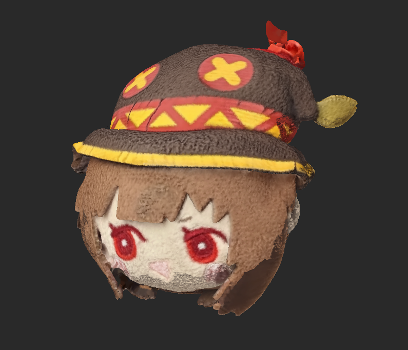
Megumin Keychain
A detailed 3D scan of my Megumin anime character keychain. The Revopoint scanner successfully captured the intricate details of the character's hat, facial features, and textured surfaces. The scan demonstrates the scanner's ability to handle complex geometry and small details.
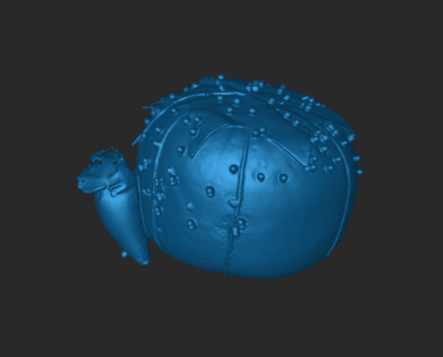
Velvet Tomato Plushie
A 3D scan of a soft velvet tomato plushie. This scan presented an interesting challenge for the Revopoint scanner, as soft, fuzzy materials can be difficult to capture with structured light scanning. The resulting model shows the scanner's capability to handle varied surface textures.
3D Scanning Insights
The Revopoint scanner with Revoscan software provided an accessible way to digitize real-world objects. The structured light scanning technology captures geometry by projecting patterns onto objects and analyzing their deformation. The software automatically generates both point cloud data (raw scan points) and mesh models (connected surfaces), making the scans ready for use in 3D modeling applications.
Scanning Challenges
- • Soft, fuzzy materials (like the velvet tomato) can be difficult for structured light
- • Requires adequate lighting and stable scanning environment
- • Small objects need careful positioning for complete coverage
Applications
- • Reverse engineering existing objects
- • Creating digital archives of physical items
- • Reference models for 3D modeling and design
- • Quality control and measurement verification
Reflection
Creating the first physical component of my final project was an exciting milestone that transformed abstract CAD designs into tangible reality. The 3D printing process revealed important lessons about manufacturing tolerances and the gap between digital precision and physical fabrication. While the dimensional accuracy issue required manual post-processing, it taught me to design with real-world manufacturing constraints in mind.
This pan-tilt base establishes the foundation for the complete AI turret system. The successful integration of the gear system and servo motor demonstrates that the mechanical design is sound and ready for the next phase: building the tilt mechanism and trigger assembly. The experience reinforced that iterative prototyping and hands-on problem-solving are essential skills in digital fabrication, complementing CAD design expertise.