Arduino-Controlled Kinetic Sculpture
Building on Week 3's kinetic sculpture depicting the thief on the cross by adding Arduino-based speed control through a potentiometer, upgrading to wood construction, and solving mechanical friction challenges.
Project Overview
Iteration & Improvement
This project builds upon Week 3's kinetic sculpture by adding microcontroller-based speed control and implementing significant material and design improvements. Using an ESP32 microcontroller and a potentiometer, the sculpture now features variable-speed control, allowing users to adjust the oscillation rate of the resurrection movement in real-time.
New Features
- • ESP32 microcontroller integration
- • Potentiometer-based speed control
- • Arduino programming for motor control
- • Real-time variable speed adjustment
Material Upgrades
- • 6mm plywood instead of cardboard
- • Wood yoke replacing copper wire
- • Improved hole tolerances and sizing
- • M3, M4, and M5 screws for assembly
Live Demo
Variable Speed Control in Action
Watch the Arduino-controlled sculpture in action! The potentiometer allows smooth adjustment of the motor speed, controlling how fast the figure of the thief oscillates on the cross. The improved wood construction and chamfered rails enable smooth, consistent motion without binding or excessive friction.
Construction & Assembly
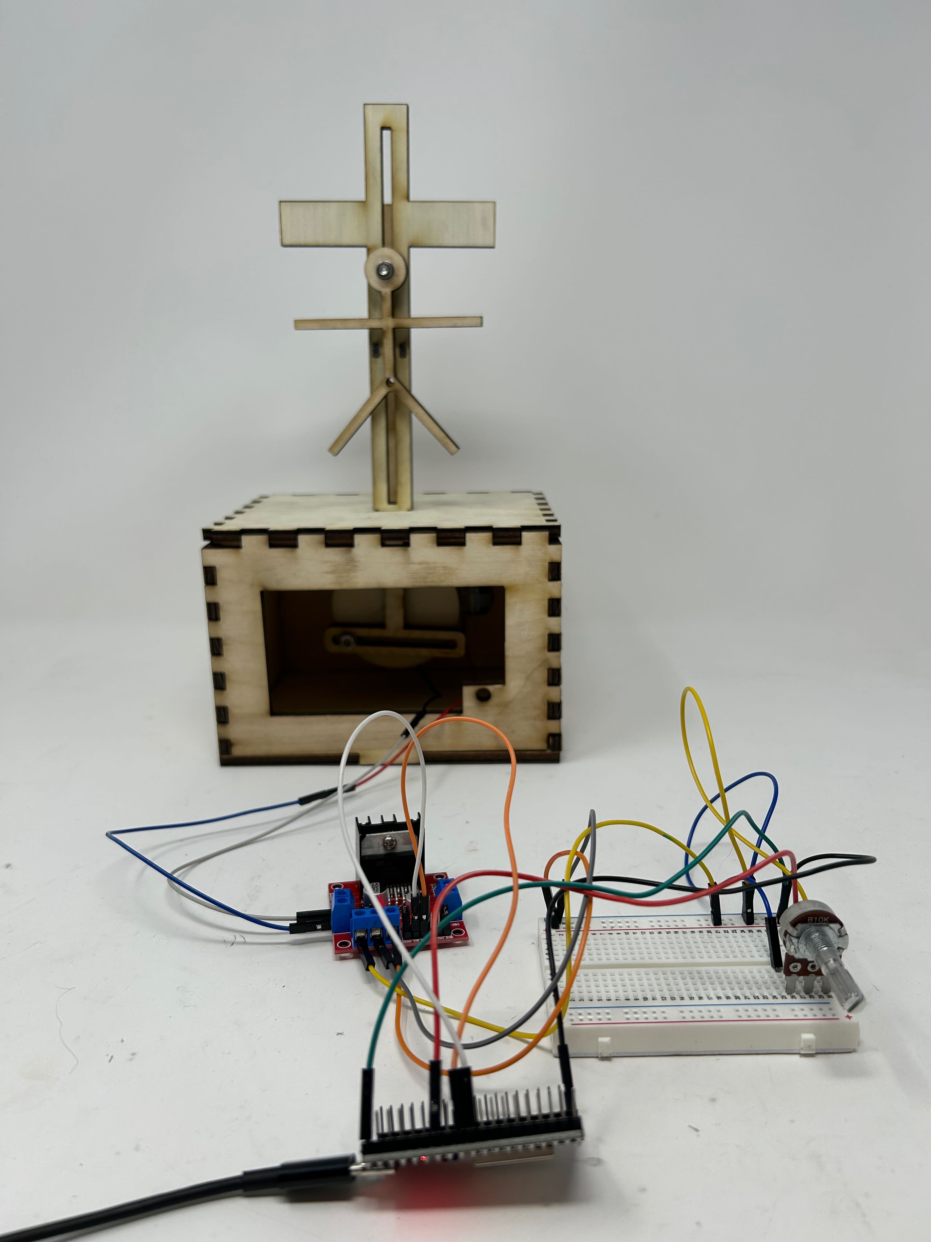
Complete Assembly
The finished sculpture showcasing the upgraded wood construction and integrated electronics. The 6mm plywood provides significantly better structural rigidity compared to the cardboard version, while the hot glue assembly creates strong joints between panels.
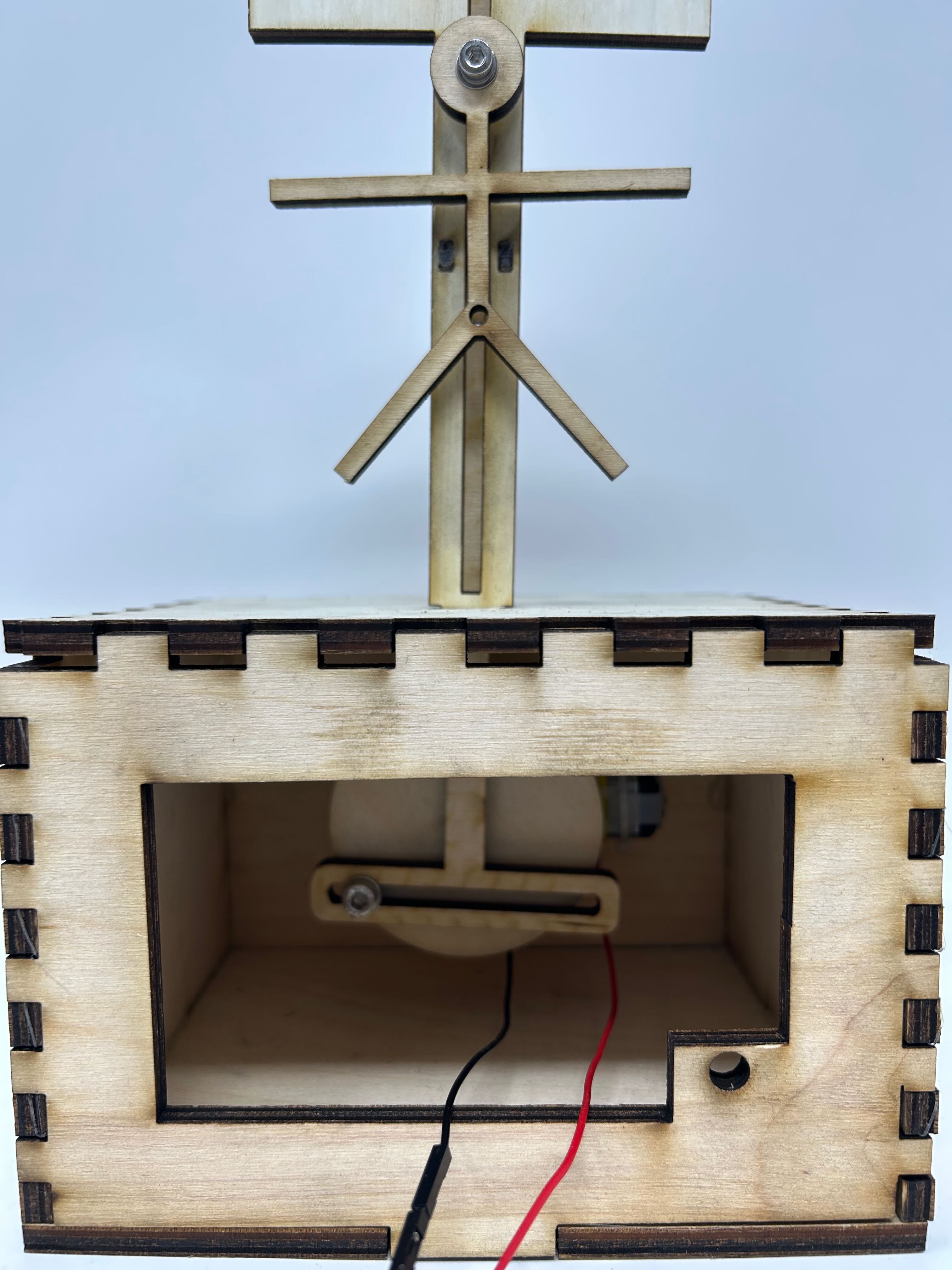
Front View - Housing
Front view of the plywood housing showing the clean laser-cut edges and cross structure. The wood material provides a more durable and aesthetically pleasing appearance while maintaining the same geometric design from the CAD model.
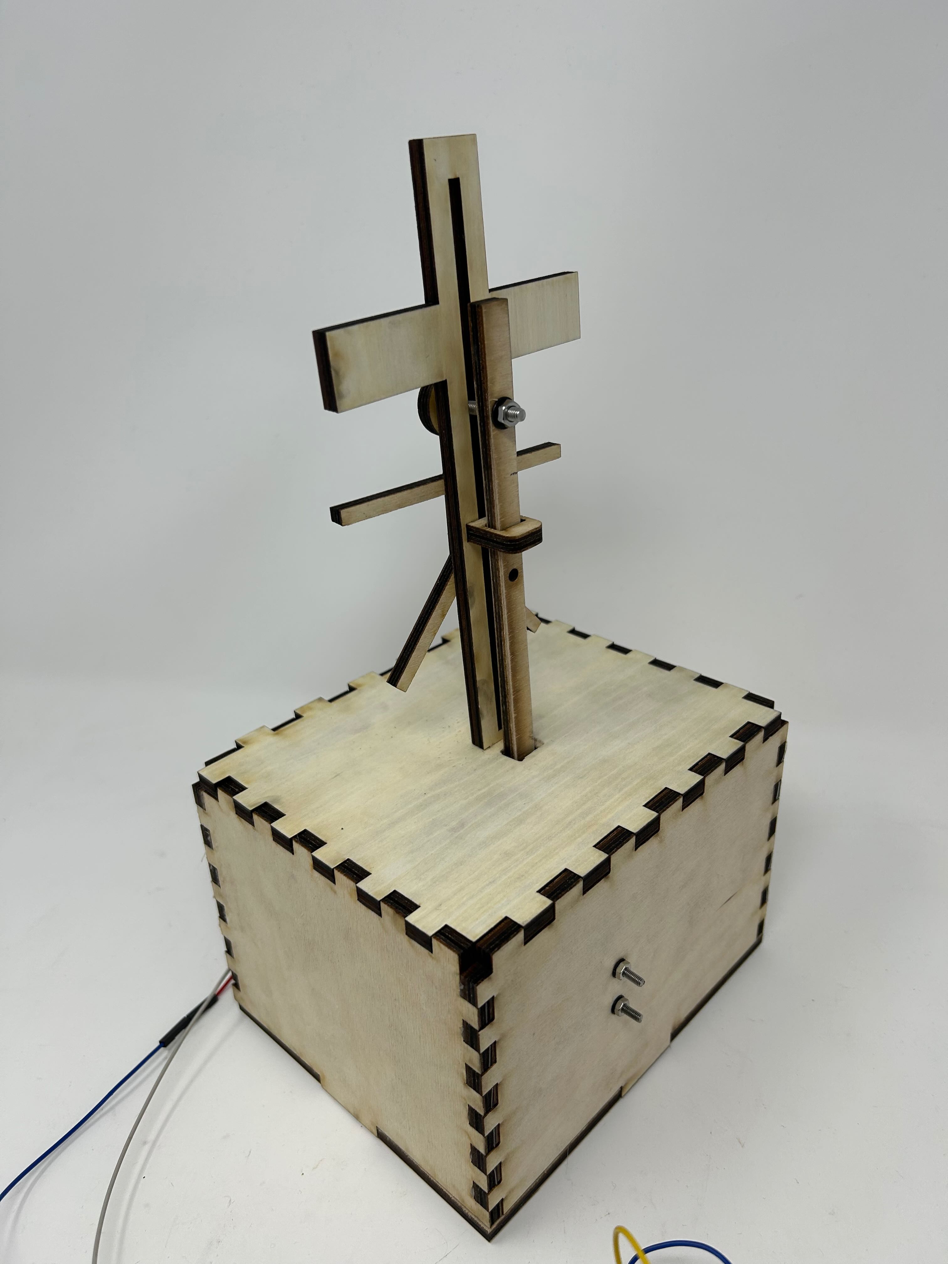
Back View - Mechanism Access
Rear view revealing the internal scotch yoke mechanism and how the wood yoke replaced the copper wire design. The chamfered rail edges visible here were crucial for reducing friction and enabling smooth motion throughout the full range of travel.
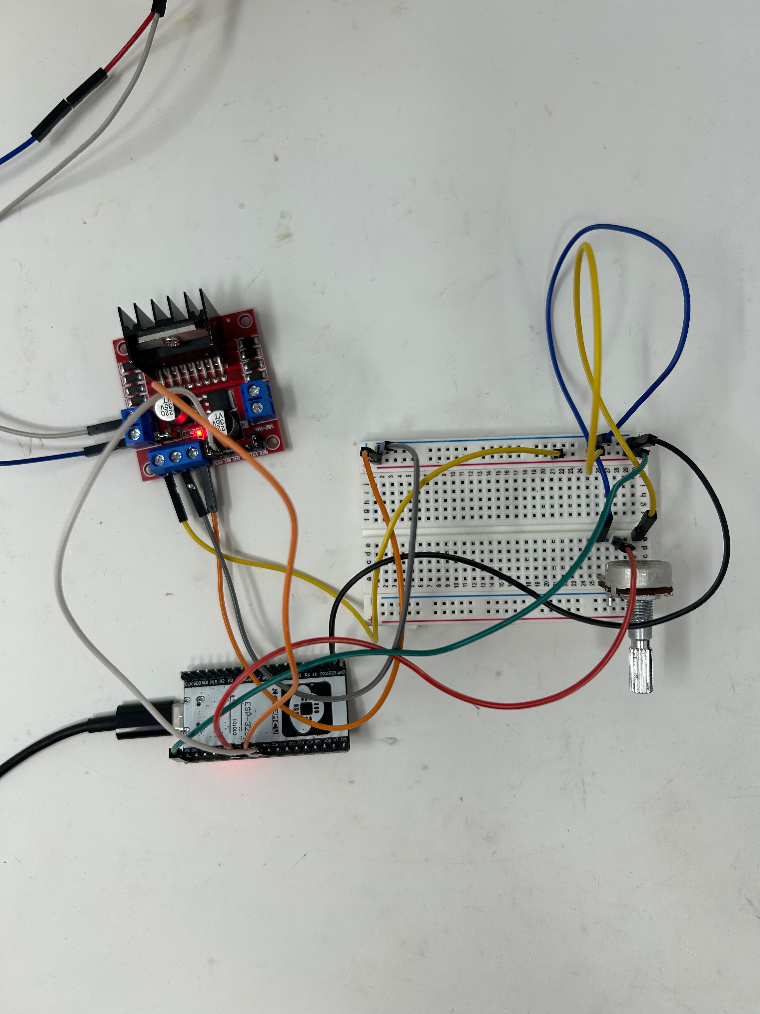
Control Circuit
The ESP32 microcontroller connected to the potentiometer and DC motor. The potentiometer (pin 12) reads analog values from 0-4095, which are mapped to PWM duty cycles of 0-255 to control motor speed. The motor control pins (26 and 27) handle speed and direction.
Circuit Diagram
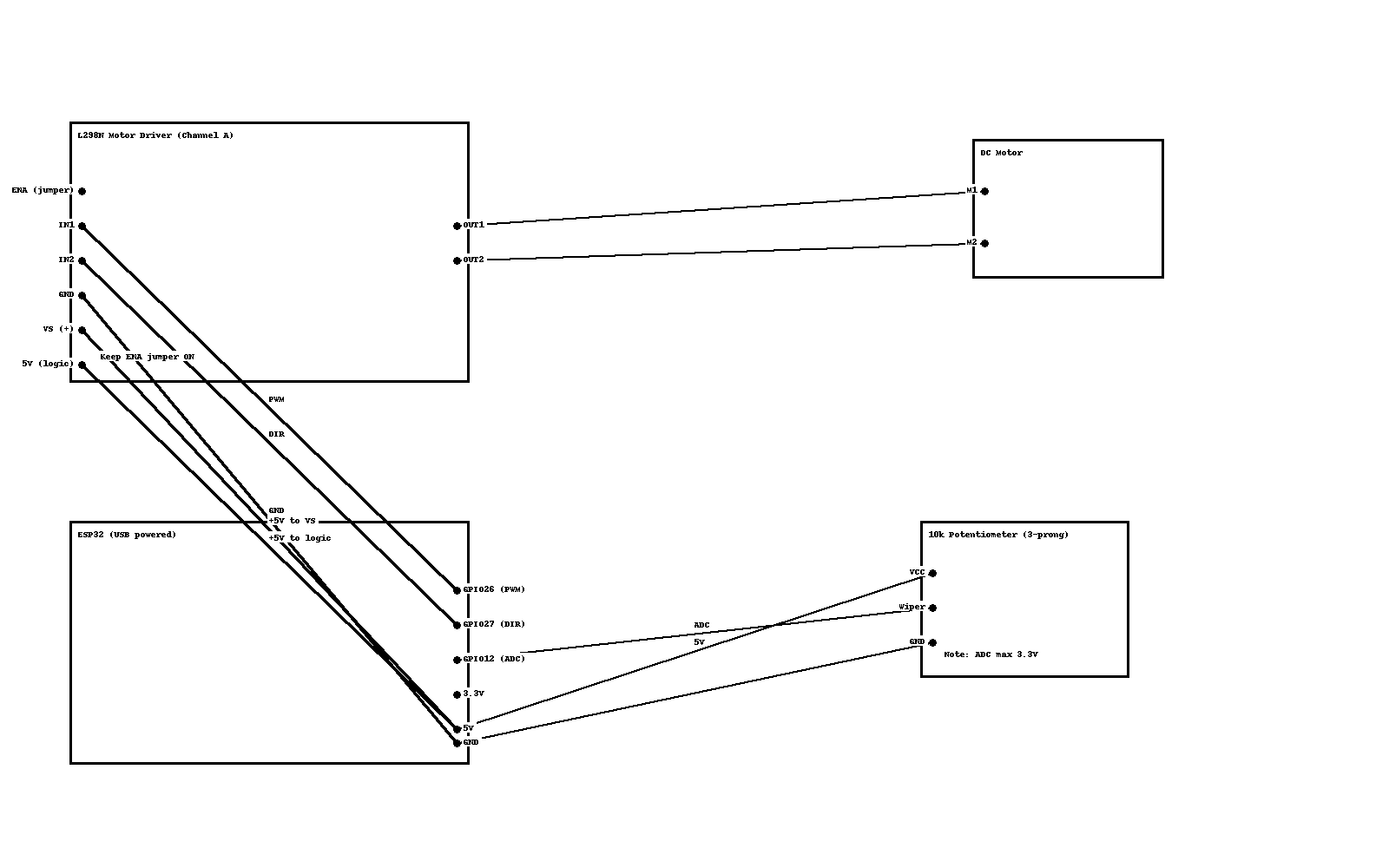
Complete Wiring Schematic
The circuit diagram shows the complete wiring between the ESP32 microcontroller, L298N motor driver, DC motor, and potentiometer. The L298N motor driver (Channel A) interfaces between the ESP32's logic-level signals and the motor. Both the motor controller and potentiometer are powered by the ESP32's 5V pin, simplifying the power distribution in this compact design.
Motor Control
- •
OUT1/OUT2: Motor terminals - •
ENA (Pin 26): PWM speed control - •
IN1 (Pin 27): Direction control
Power Supply
- •
5V: Powers L298N and potentiometer - •
GND: Common ground - • All powered from ESP32 5V pin
Potentiometer
- •
VCC: 5V from ESP32 - •
Wiper (Pin 12): Analog input - •
GND: Ground connection
Arduino Programming
Motor Control Code
The Arduino sketch uses PWM (Pulse Width Modulation) to control motor speed based on potentiometer input. The ESP32 reads analog values from the potentiometer and maps them to appropriate PWM duty cycles for smooth speed control.
const int A1A = 26; // PWM Speed
const int A1B = 27; // direction
int motorVal; // motor

// potentiometer pins
int potPin = 12;
int potVal;

// setting PWM properties
const int freq = 5000;
const int resolution = 8;

void setup() {
  pinMode(A1A, OUTPUT); // specify these pins as outputs
  pinMode(A1B, OUTPUT);

  pinMode(potPin, INPUT); // specify these pins as inputs

  ledcAttach(A1A, freq, resolution);
  ledcWrite(A1A, 0);   // start with the motors off
}

void loop() {
  potVal = analogRead(potPin); // read pot value
  motorVal = map(potVal, 0, 4095, 0, 255); // map pot reading to 0-255 scale
  motorA(LOW, motorVal);  // turn motor CW depending on pot value
}


// This is a custom function to drive Motor A
// inputs: direction (HIGH/LOW), speed (0-255)
// outputs: motor control

void motorA(byte d, int s) {
  if(d == 1){
    ledcWrite(A1A, 255-s);
    digitalWrite(A1B, HIGH);
  } else if (d == 0){
    ledcWrite(A1A, s);
    digitalWrite(A1B, LOW);
  }
}
Code Explanation
Pin Configuration
- •
Pin 26 (A1A): PWM speed control - •
Pin 27 (A1B): Motor direction - •
Pin 12: Potentiometer input
PWM Settings
- •
Frequency: 5000 Hz - •
Resolution: 8-bit (0-255) - •
Input Range: 0-4095 (12-bit ADC)
How It Works
- The potentiometer is read using
analogRead(), returning values from 0 to 4095 - The
map()function converts this to 0-255 for PWM duty cycle - The
motorA()function sets direction (LOW for one direction) and speed - PWM controls motor speed smoothly across the full range based on potentiometer position
Improvements from Week 3
CAD Model Refinements
While reusing the same base CAD model from Week 3, I made critical modifications to improve functionality and reduce friction:
- • Adjusted hole placement for better component alignment
- • Increased hole sizes for reduced friction on moving parts
- • Optimized tolerances for wood material properties
- • Planned for M3, M4, and M5 screw mounting points
Material Upgrade: Plywood
Switching from 6mm cardboard to 6mm plywood brought significant improvements:
- • Much greater structural rigidity and durability
- • Cleaner laser-cut edges with no fraying
- • Better dimensional stability (no warping)
- • More professional appearance
- • Stronger mounting points for screws
Assembly Method Changes
The construction approach evolved significantly from the Week 3 cardboard version:
Structural Assembly
Hot glue replaced finger joints for the box assembly, providing faster construction and stronger bonds with the plywood material.
Moving Parts
M3, M4, and M5 screws were used for all moving parts and motor mounting, providing adjustable, secure connections that can be disassembled for maintenance.
Wood Yoke
The copper wire yoke was replaced with a laser-cut wood yoke, providing better strength and more precise geometry for the scotch yoke mechanism.
Motor Mounting
Properly sized screw holes allowed for secure motor mounting with metal screws, eliminating the instability issues from the Week 3 version.
Challenges & Solutions
Challenge: Excessive Friction
The primary challenge was excessive friction in the scotch yoke mechanism. The wood yoke would bind against the rails, preventing smooth motion and causing the motor to stall or move erratically. Writing the program was straightforward, but getting the moving parts to move smoothly proved to be much more difficult due to excessive friction between components.
Solution: Chamfered Rails
The solution was to chamfer the edges of the scotch yoke rails. This reduced contact area and eliminated sharp edges that were creating excessive drag.
- • Reduced surface contact between yoke and rails
- • Eliminated binding at entry/exit points
- • Enabled smooth motion throughout full travel
- • Maintained structural integrity of mechanism
Programming vs. Mechanical Engineering
This project highlighted an important lesson: in mechatronics projects, the software is often the easiest part. The Arduino code was straightforward and worked correctly on the first try. The real challenge was in the mechanical design - ensuring proper tolerances, managing friction, and creating reliable physical connections. Success required iteration and hands-on problem-solving with the physical mechanism until the motion was smooth and reliable.
Technical Specifications
Materials
- • 6mm plywood sheets
- • Wood yoke component
- • Hot glue assembly
- • M3, M4, M5 screws
Electronics
- • ESP32 microcontroller
- • DC motor with driver
- • Potentiometer (pin 12)
- • PWM control (5kHz, 8-bit)
Fabrication
- • Laser-cut plywood parts
- • Chamfered rail edges
- • Modified CAD tolerances
- • Precision screw holes
Reflection
This project demonstrated the power of iteration in engineering design. By building upon Week 3's foundation, I could focus on specific improvements rather than starting from scratch. The material upgrade to plywood dramatically improved durability and aesthetics, while the Arduino integration added meaningful interactivity through speed control.
The most valuable lesson was understanding that successful mechatronics requires balancing software and hardware skills. While the Arduino programming came naturally and worked immediately, solving the mechanical friction issues required careful analysis, experimentation with chamfering techniques, and hands-on problem-solving. This experience reinforced that physical prototyping and iteration are just as important as clean code in creating functional interactive systems.