Kinetic Sculpture: The Thief on the Cross
Creating a motorized kinetic sculpture using a scotch yoke mechanism to depict the thief who was crucified alongside Jesus, with vertical movement symbolizing his final moments.
Project Concept
The Thief on the Cross: A Kinetic Sculpture
This kinetic sculpture depicts the thief who was crucified on the left side of Jesus. Using a scotch yoke mechanism driven by a DC motor, the sculpture creates a continuous vertical motion that raises and lowers the figure on the cross, representing the struggle and suffering of crucifixion. The piece explores themes of mortality, judgment, and the human condition through mechanical movement.
Design Concept
- • Scotch yoke mechanism for linear motion
- • DC motor for continuous rotation
- • Vertical movement symbolizing resurrection
- • 6mm cardboard construction with finger joints
Technical Requirements
- • Motorized movement with power source
- • Laser-cut precision components
- • Soldered structural connections
- • Secure mechanical attachments
Working Sculpture
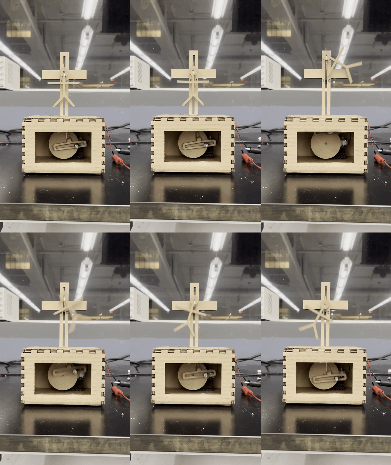
Kinetic Movement in Action
The completed kinetic sculpture demonstrates smooth vertical movement through the scotch yoke mechanism. The continuous motion creates a mesmerizing effect that represents the final struggles of the thief on the cross, drawing viewers into contemplating themes of suffering, mortality, and human nature. The motorized system operates reliably with proper mechanical connections.
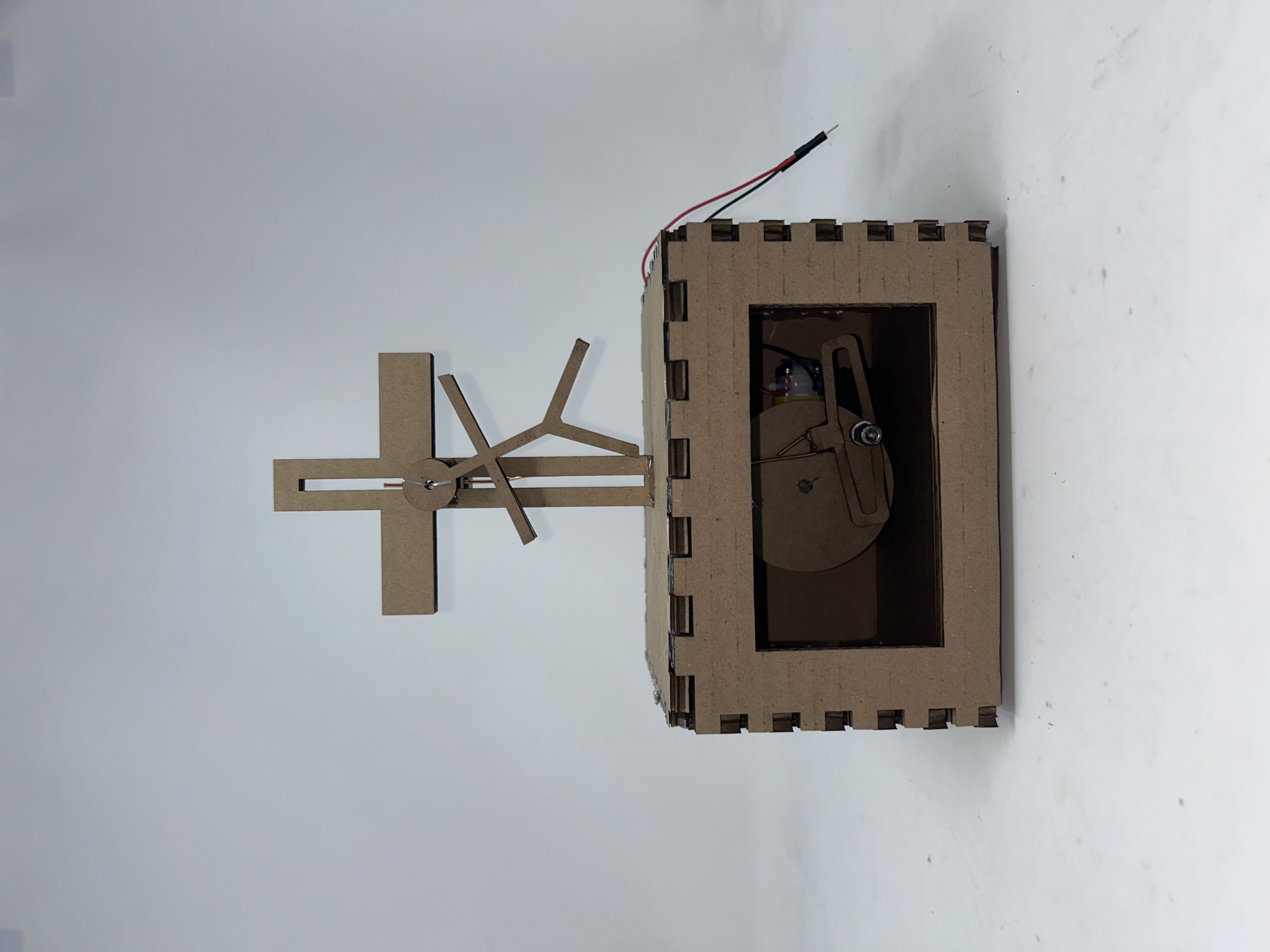
Front View - Complete Assembly
The front view shows the complete kinetic sculpture with the cross and figure positioned for optimal visibility. The clean lines of the laser-cut cardboard create an elegant silhouette that emphasizes the spiritual symbolism while showcasing the mechanical precision.
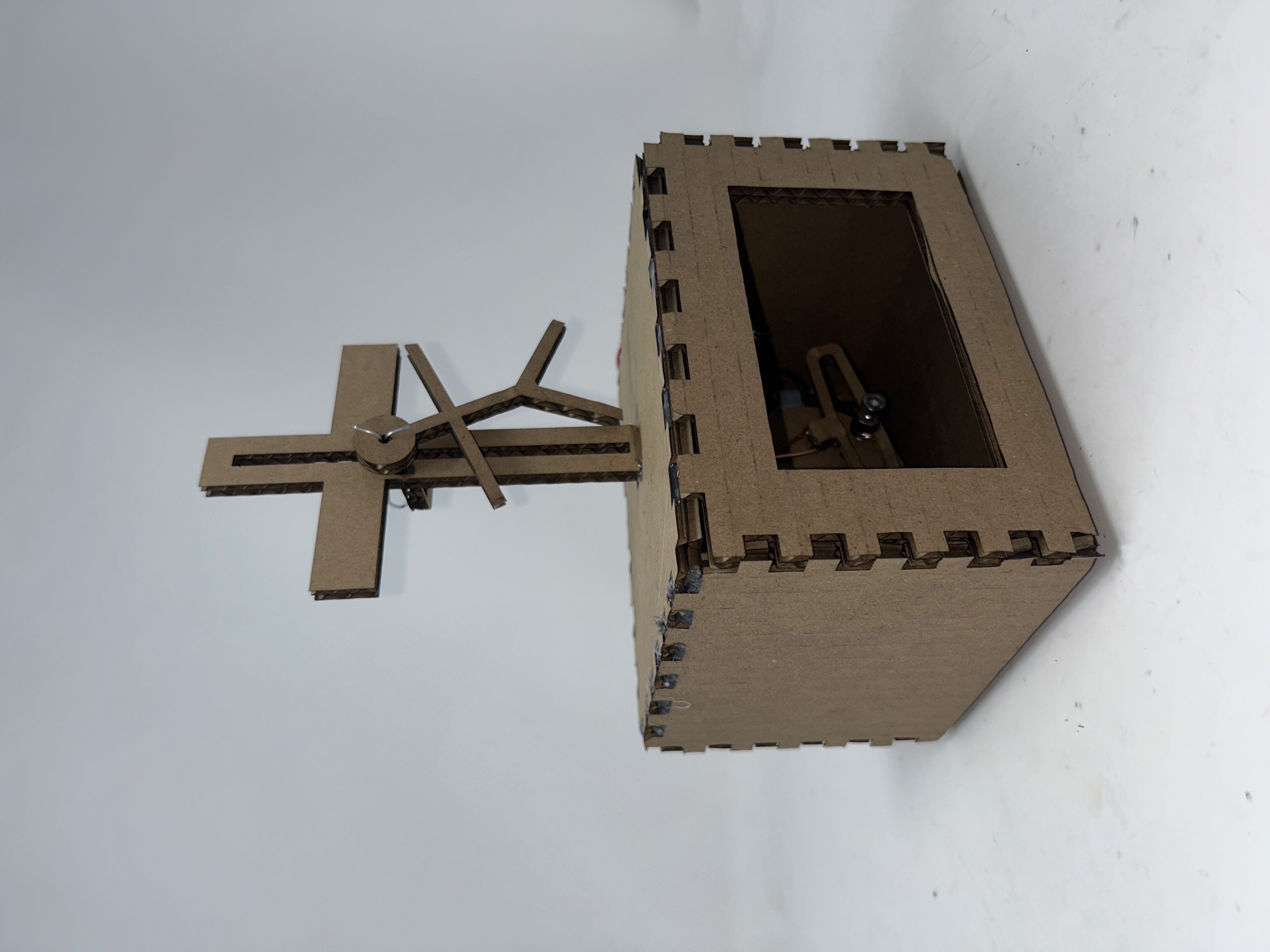
Front Diagonal Perspective
This diagonal view reveals the three-dimensional nature of the sculpture and shows how the mechanism housing integrates with the cross structure. The perspective demonstrates the careful consideration of proportions and visual balance in the overall design.
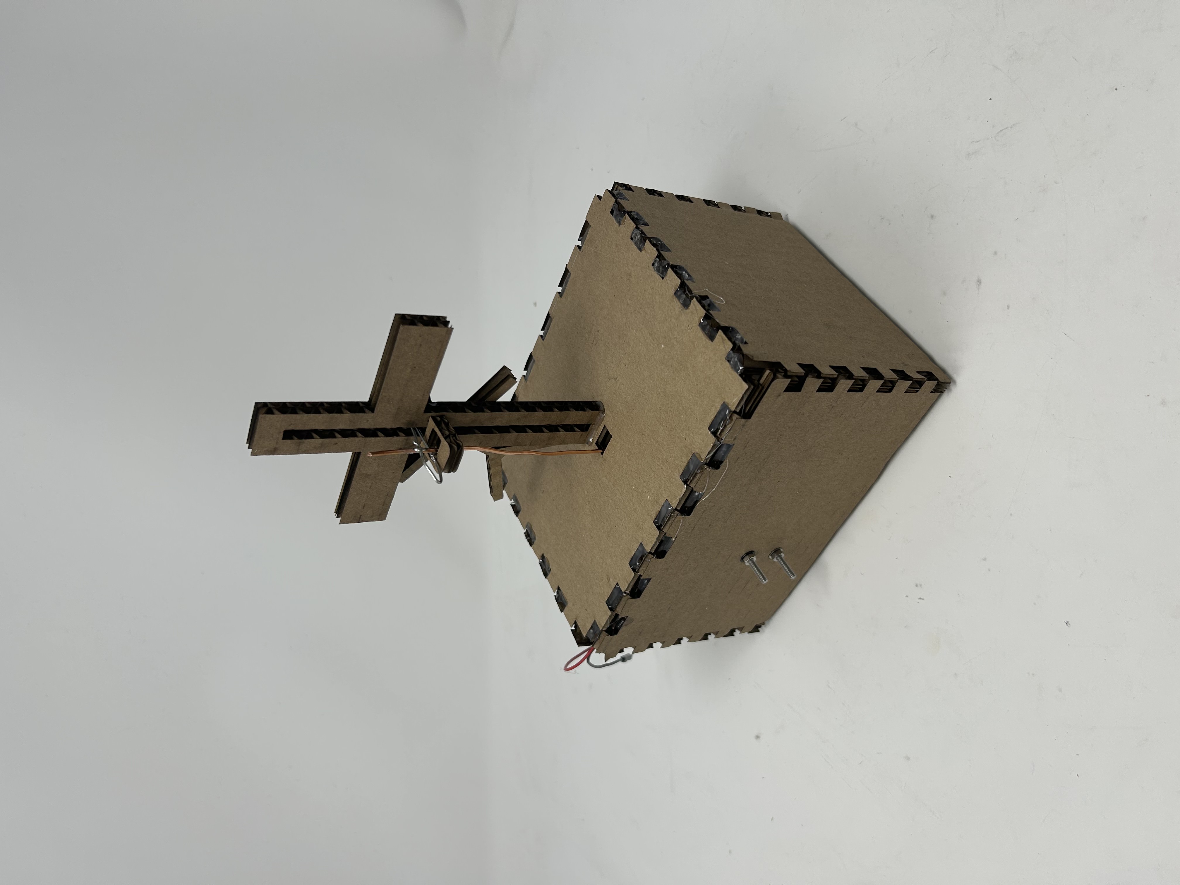
Top Angle - Housing Construction
The top angle view shows the back of the sculpture housing, revealing the clean construction and how the cardboard components fit together. This perspective demonstrates the structural design while maintaining the artistic integrity of the piece.
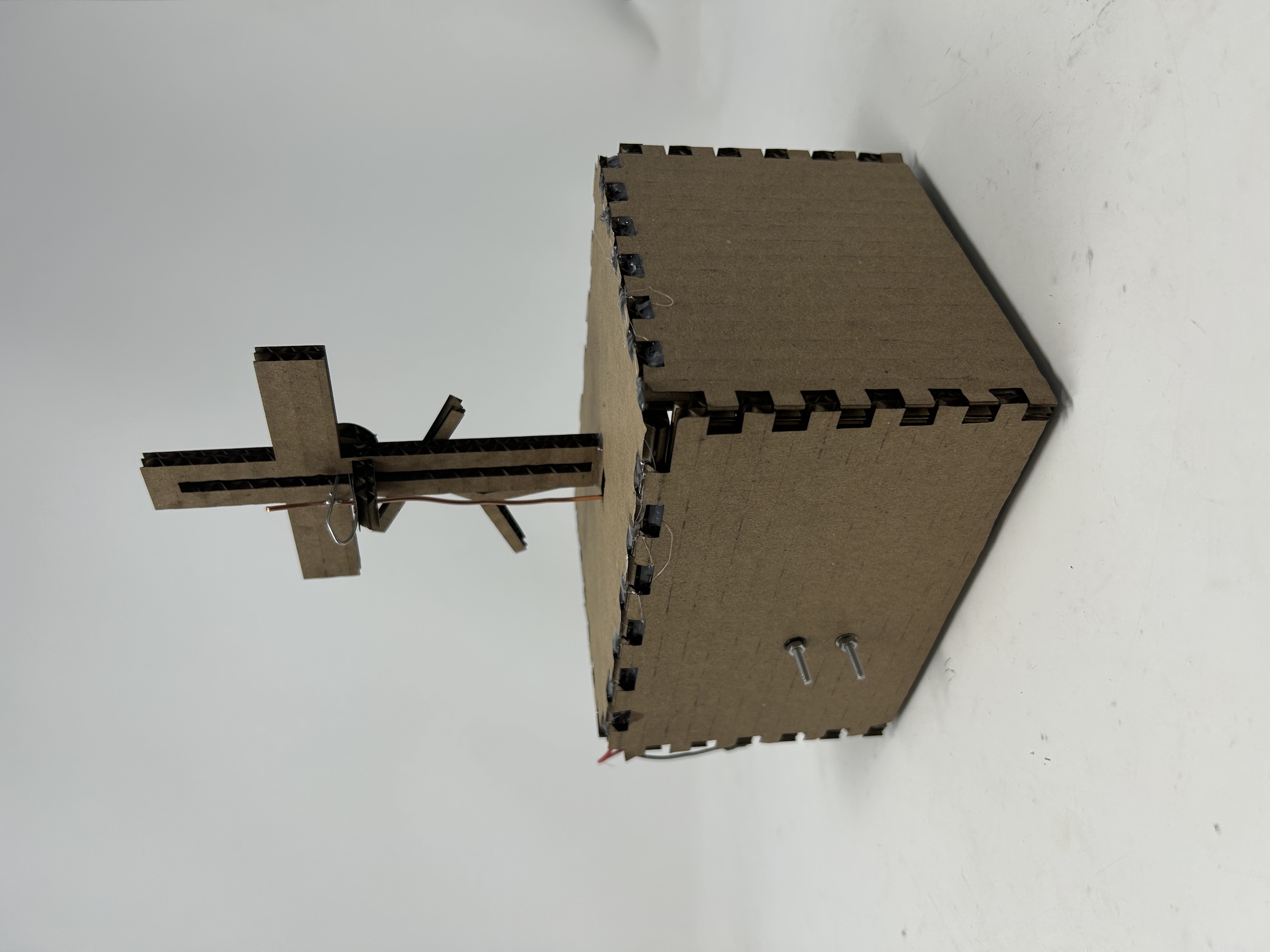
Back Angle - Construction Details
The rear perspective shows the finger joint construction method inherited from Week 2's box project, demonstrating how previous learning was applied to create the housing for this more complex kinetic mechanism.
CAD Design & Mechanism
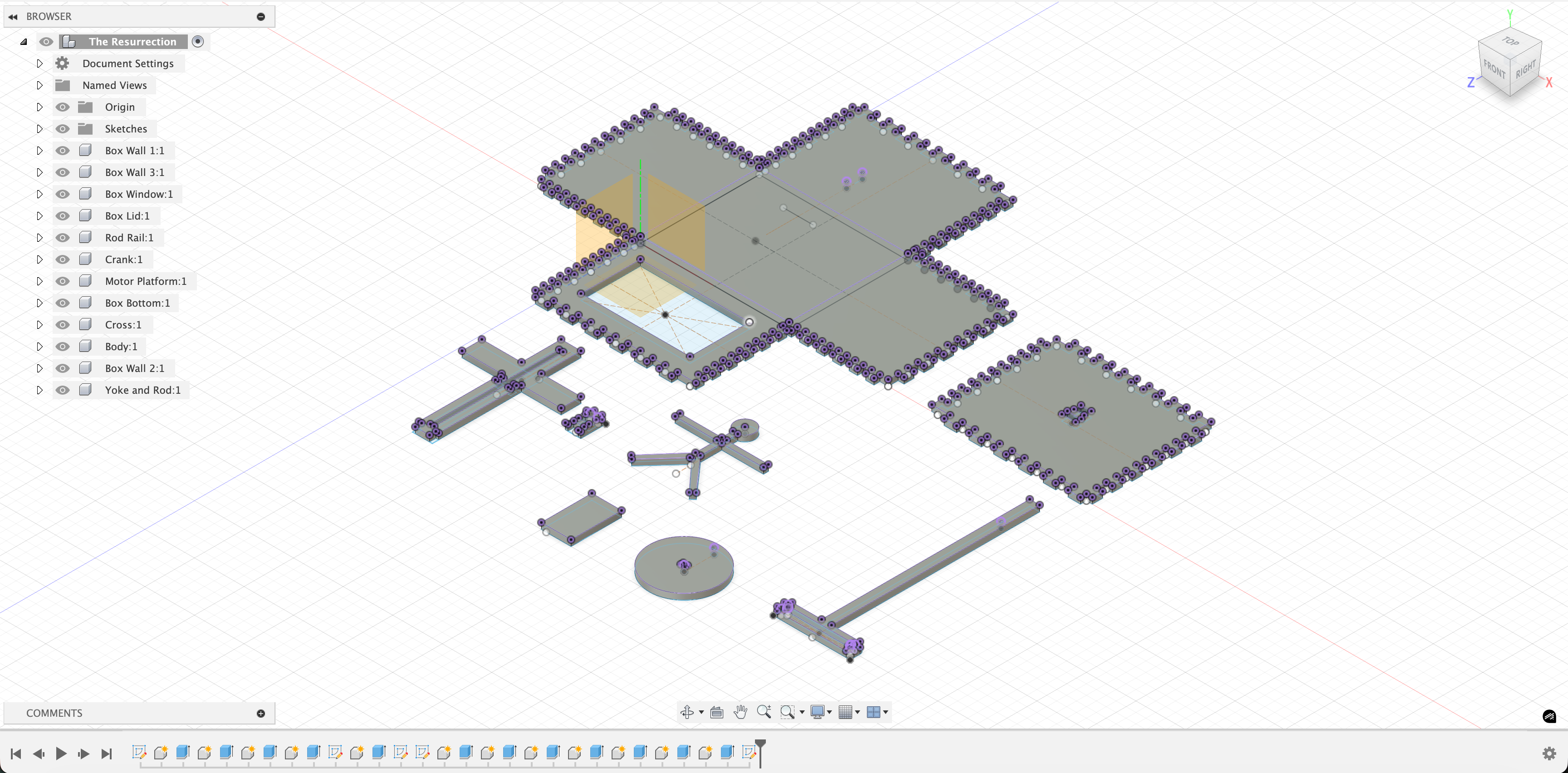
Fusion 360 CAD Model
The complete CAD model designed in Fusion 360 shows the scotch yoke mechanism integrated with the cross structure and housing. This digital model was essential for planning the laser cutting layout, calculating proper tolerances, and visualizing how all components would fit together before fabrication. The parametric design allowed for easy adjustments during the iterative design process.
Scotch Yoke Mechanism Design
The scotch yoke mechanism converts the rotational motion of the DC motor into linear vertical motion. This mechanical system consists of a rotating crank connected to a sliding yoke that moves up and down along a linear path. The mechanism provides smooth, sinusoidal motion that evokes the rising and falling movements of a person struggling on the cross.
Mechanism Components
- • DC motor for rotational input
- • Crank arm attached to motor shaft
- • Sliding yoke with linear constraints
- • Connecting rod between crank and yoke
Construction Materials
- • 6mm cardboard for housing and structure
- • Copper wire for structural frame connections
- • Metal screws for motor mounting
- • Washers and nuts for secure attachment
Laser Cutting & Assembly
Using the same 6mm cardboard and finger joint techniques from Week 2, I laser-cut all the structural components for the kinetic sculpture housing. The precision of laser cutting was essential for creating the mounting holes for screws and ensuring proper alignment of the mechanism components. The soldering process was used to join the copper wire frame together, creating strong structural connections for the mechanical components of the scotch yoke mechanism.
Learning Through Failure
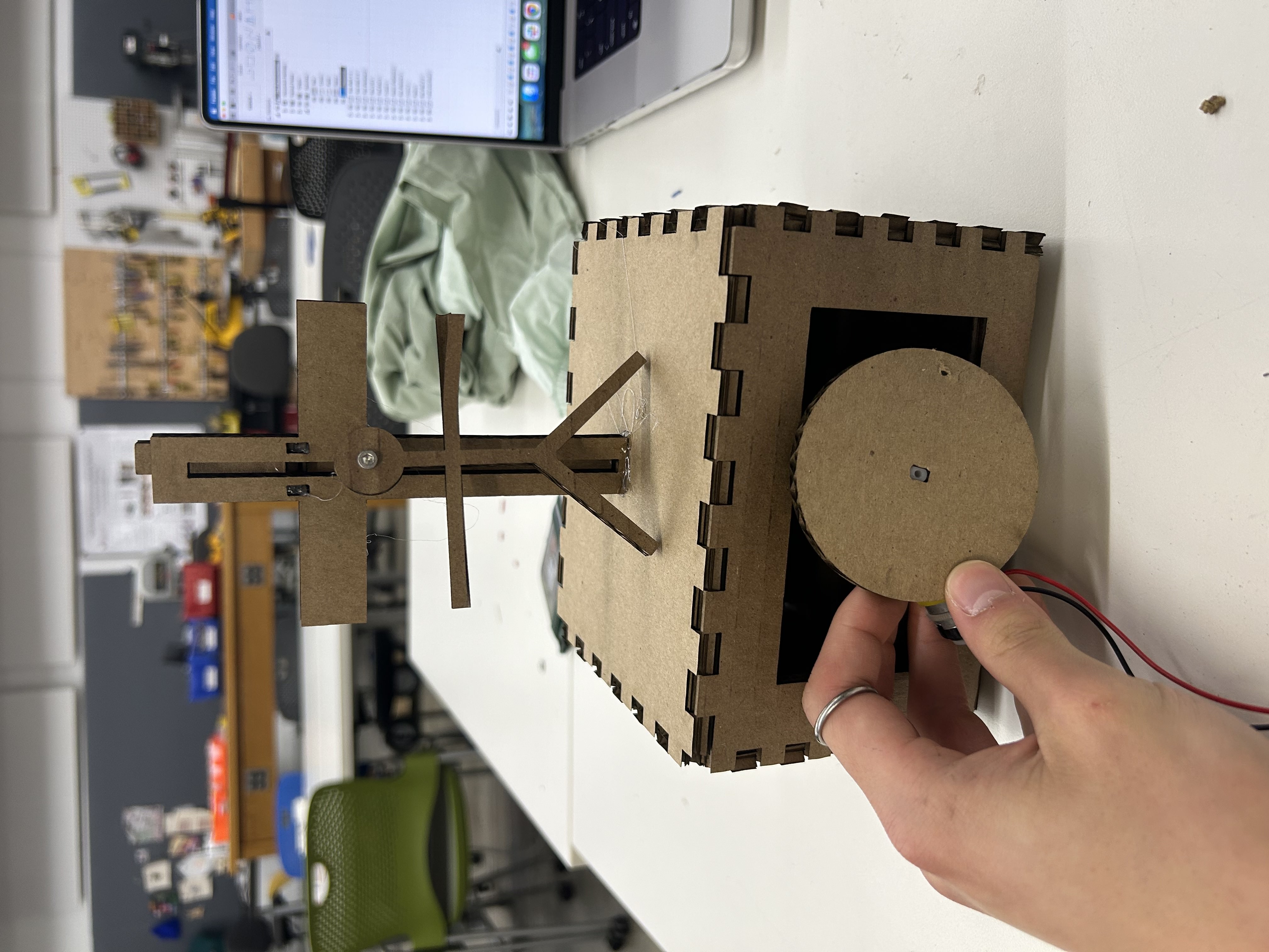
First Attempt: Critical Failures
The initial attempt revealed several critical design flaws that prevented the mechanism from functioning properly. This failure became an invaluable learning experience that informed the successful redesign and highlighted the importance of proper mechanical connections and material selection.
Problems Identified
- No proper holes for motor mounting screws - motor was unstable
- Used cardboard for structural frame connections - too flimsy and unreliable
- Yoke not securely attached to crank - mechanism would bind and fail
- Overall structural instability due to poor connections
Solutions Implemented
- Laser-cut precise holes for screw mounting - secure motor attachment
- Switched to copper wire for structural frame - flexible and reliable connections
- Added washers and nuts for secure yoke-to-crank attachment
- Reinforced all critical connection points for stability
Iterative Design Process
This failure taught me that successful kinetic sculptures require careful attention to every mechanical connection point. The transition from the broken first attempt to the working version demonstrated the importance of proper fasteners, appropriate materials for different functions, and the need for structural analysis in mechanical design. Each problem became a learning opportunity that improved the final result.
Technical Specifications
Materials
- • 6mm corrugated cardboard
- • Copper wire connections
- • Metal screws and washers
- • Nuts for secure fastening
Electronics
- • DC motor for rotation
- • Power source connection
- • Soldered wire frame joints
- • Mechanical linkage system
Mechanism
- • Scotch yoke linear motion
- • Finger joint construction
- • Precision laser-cut holes
- • Washers and nuts assembly
Key Learnings
Material Properties Matter
Cardboard, while excellent for structural components, proved inadequate for dynamic mechanical connections. Its tendency to become flimsy and behave erratically under continuous motion taught me to carefully consider material properties for each application within a design.
Attachment Methods Are Critical
The difference between failure and success came down to proper attachment methods. Using appropriate fasteners like washers and nuts instead of relying solely on cardboard connections was essential for creating reliable mechanical systems.
Precision in Fabrication
The laser cutter's precision was crucial for creating exact mounting holes for screws and ensuring proper alignment of moving parts. This project reinforced the importance of planning for assembly during the design phase and considering how each component will be manufactured and connected.
Reflection
Creating this kinetic sculpture was a profound learning experience that combined mechanical engineering, electronics, and artistic expression. The initial failure taught me more about proper design practices than a successful first attempt would have. The project demonstrated that creating reliable kinetic art requires understanding material properties, mechanical principles, and precise fabrication techniques. Most importantly, it showed me that the iterative design process - learning from failure and improving - is fundamental to creating successful mechanical systems. The final working sculpture not only achieved its technical goals but also created a meaningful artistic statement about resurrection and renewal.