CAD Modeling & Laser Cutting
Learning Fusion 360 to design a pentagonal prism box and fabricating it using laser cutting on 6mm cardboard.
Project Overview
Pentagonal Prism Box Design
This week I dove into CAD modeling using Fusion 360 to design a pentagonal prism box. As someone new to CAD software, I found the initial learning curve challenging but rewarding. The goal was to create a functional box with proper tolerances for laser cutting that would assemble correctly on the first try.
Design Challenges
- • Learning Fusion 360 interface and tools
- • Understanding pentagonal geometry
- • Calculating proper joint tolerances
- • Planning for 6mm cardboard thickness
Success Factors
- • Precise measurements and constraints
- • Proper finger joint design
- • First iteration fit perfectly
- • Clean laser cutting results
CAD Design Process
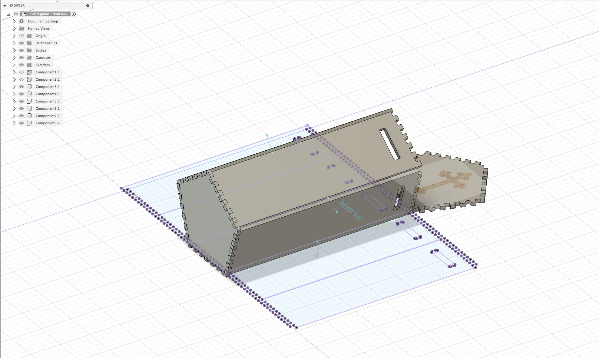
Initial Sketch Design
Started with a basic pentagonal sketch in Fusion 360. Learning to use constraints and dimensions was initially challenging, but I focused on getting the pentagon geometry correct with equal sides and proper angles (72° internal angles).
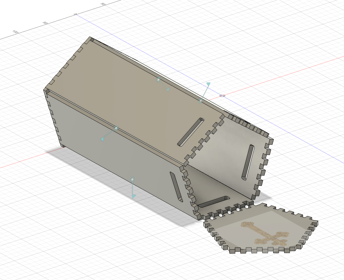
3D Assembly Model
The complete 3D model showing how all the pieces fit together. I designed finger joints for the sides and a separate bottom piece. The model helped visualize the final assembly and ensure all tolerances were correct for the 6mm cardboard material.
Learning Fusion 360
As a newcomer to CAD software, Fusion 360 initially felt overwhelming with its numerous tools and features. However, focusing on the basics of sketching, constraining, and extruding helped me create this functional design. The parametric modeling approach allowed me to easily adjust dimensions and see how changes affected the entire model.
Laser Cutting & Assembly
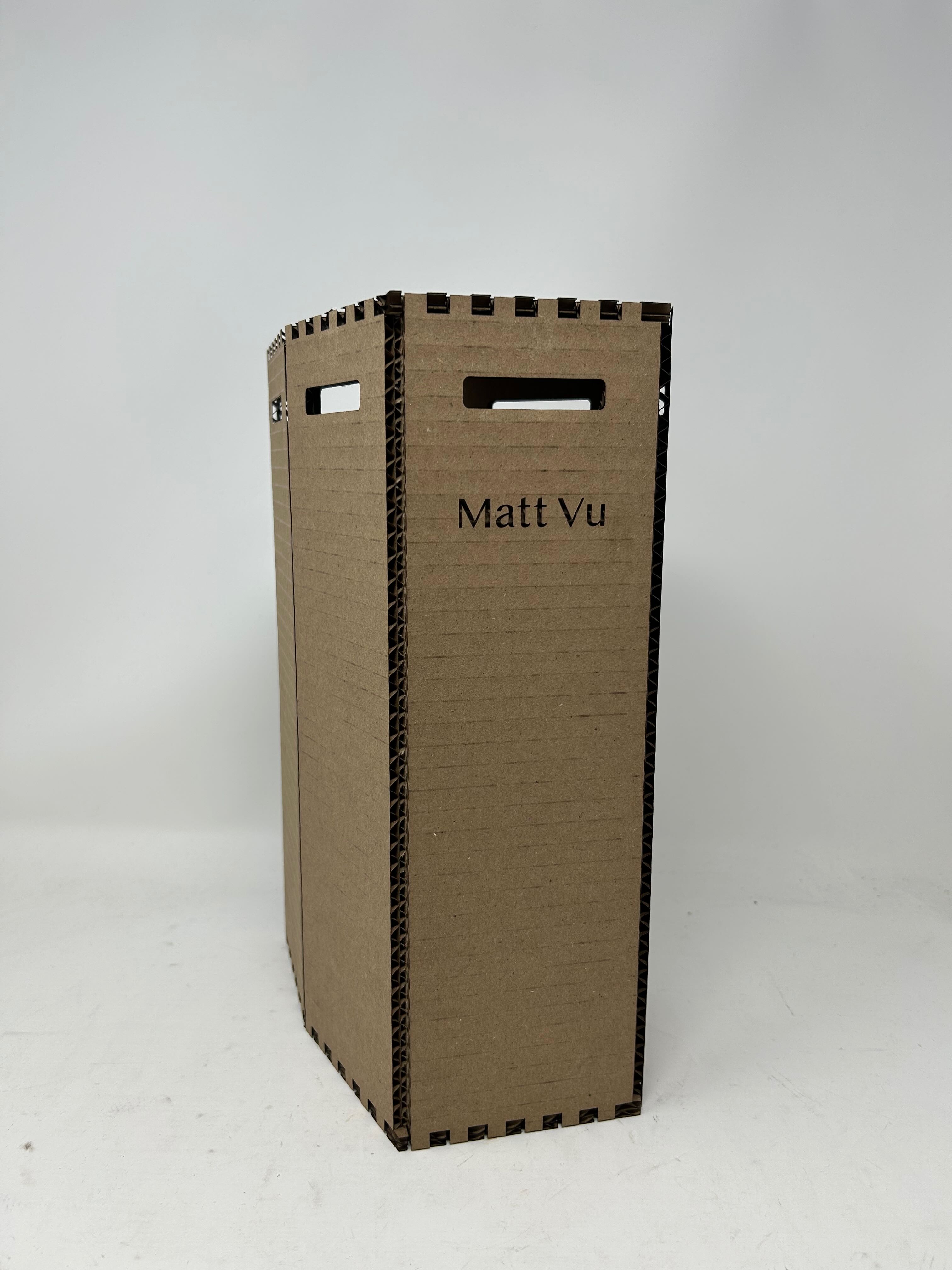
Assembled Box - Standing
The completed pentagonal prism box standing upright, showing the successful assembly. All finger joints fit perfectly on the first iteration, demonstrating the accuracy of the CAD model and proper tolerance calculations for the laser cutting process.
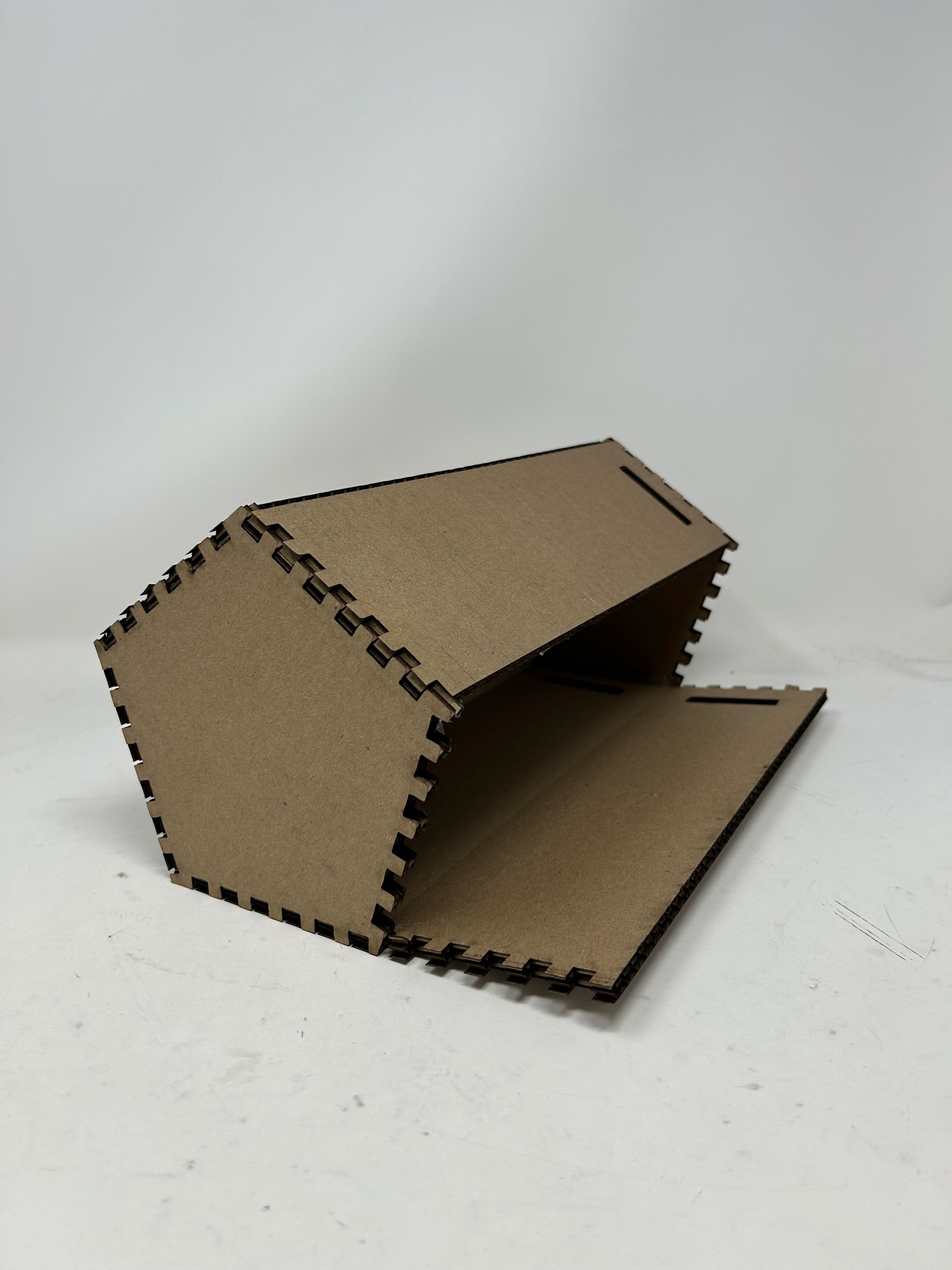
Box Interior View
Interior view showing the clean laser-cut edges and how the finger joints create a sturdy structure. The 6mm cardboard material provided good rigidity, and I added glue to the joints for extra security despite accounting for 0.2mm kerf in the design.
Laser Cutting Success
The laser cutting process went smoothly with the 6mm cardboard material. I accounted for 0.2mm kerf in my design, and the precision of the laser cutter perfectly matched the CAD model dimensions, resulting in clean cuts and well-fitting joints. I added glue during assembly for extra security and structural integrity, which was particularly satisfying as a beginner to both CAD and digital fabrication.
Download 3D Model
Pentagonal Prism Box Fusion 360 File
Download the complete Fusion 360 file for the pentagonal prism box. This file includes all the parametric sketches, extrusions, and finger joint features used to create the laser-cut design. Perfect for studying the construction method and adapting the design for your own projects.
Technical Specifications
Material
- • 6mm corrugated cardboard
- • Laser-cut precision
- • Clean, sealed edges
Geometry
- • Pentagonal base
- • 72° internal angles
- • Finger joint connections
- • 0.2mm kerf compensation
Assembly
- • Press-fit finger joints
- • Glue added for security
- • First iteration success
Fusion 360 Tutorial
Glass Soda Bottle Tutorial
To further develop my Fusion 360 skills, I followed a comprehensive tutorial on creating a glass soda bottle. This tutorial helped me understand more advanced parametric modeling techniques, including revolve features, fillets, and creating complex organic shapes that would be challenging for a beginner.
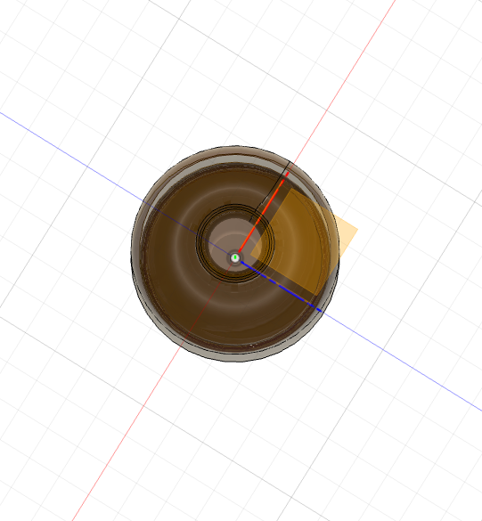
Bottle Design - Front View
The completed glass soda bottle model showing the classic bottle shape with curved surfaces and proper proportions. This tutorial taught me how to use revolve features effectively and create smooth, organic curves using splines and constraints.
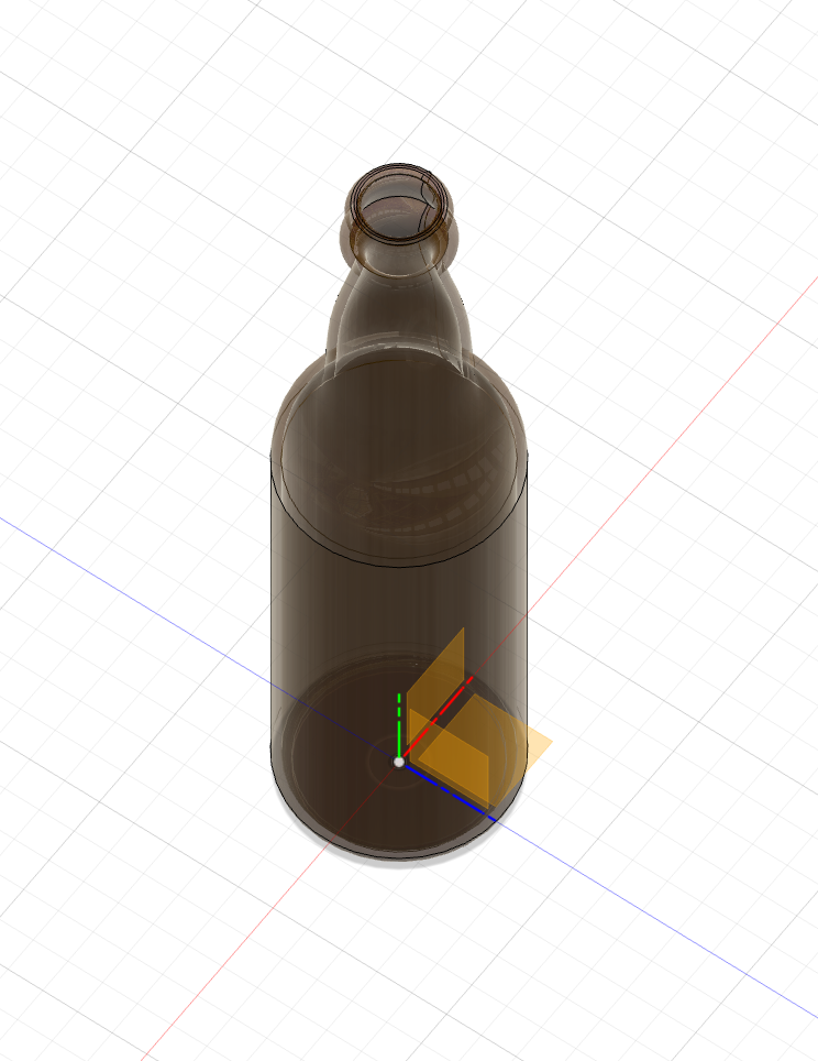
Bottle Design - Perspective View
A perspective view showcasing the 3D form and proportions of the bottle. Working through this tutorial helped me understand parametric relationships and how to modify designs efficiently by adjusting key dimensions and constraints.
Key Learning Points
New Techniques Learned
- • Revolve feature for axially symmetric objects
- • Advanced spline curve creation and editing
- • Fillet operations for smooth transitions
- • Parametric dimension relationships
Skills Developed
- • Creating complex organic shapes
- • Understanding design intent and constraints
- • Efficient workflow for iterative design
- • 3D visualization and presentation
Download 3D Model
Glass Soda Bottle Fusion 360 File
Download the complete Fusion 360 file to explore the parametric model, examine the construction history, and see how the bottle was created step-by-step. This file includes all sketches, features, and parameters used in the tutorial.
Household Object Modeling
Precision Measurement & CAD Modeling
To develop my measurement and modeling skills, I selected household objects to precisely measure with calipers and recreate in Fusion 360. This exercise taught me the importance of accurate measurement and attention to detail when reverse-engineering real-world objects into digital models.
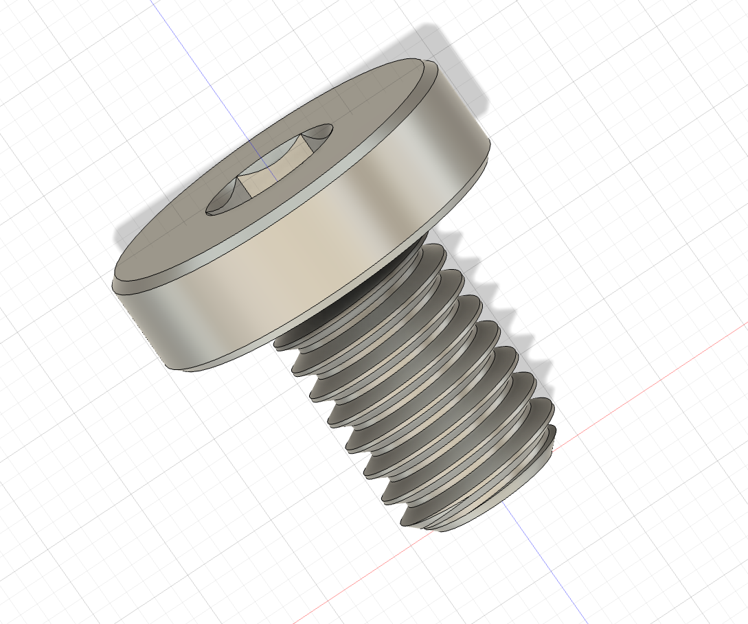
M5 Screw - Side View
Detailed model of an M5 machine screw showing the threaded shaft and hex socket head. Measured with calipers to capture precise dimensions including thread pitch, head diameter, and overall length for accurate representation.
Download Screw .f3d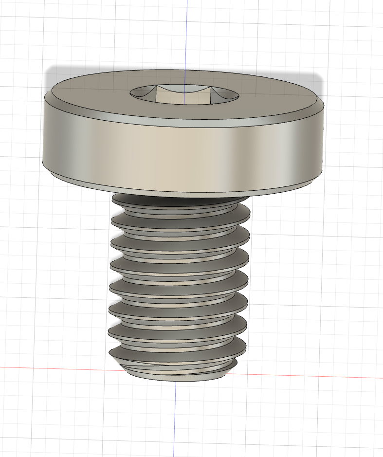
M5 Screw - Top View
Top-down view showcasing the hexagonal socket detail and circular head profile. The threaded features were created using Fusion 360's thread tool with proper M5 specifications for realistic appearance and functionality.
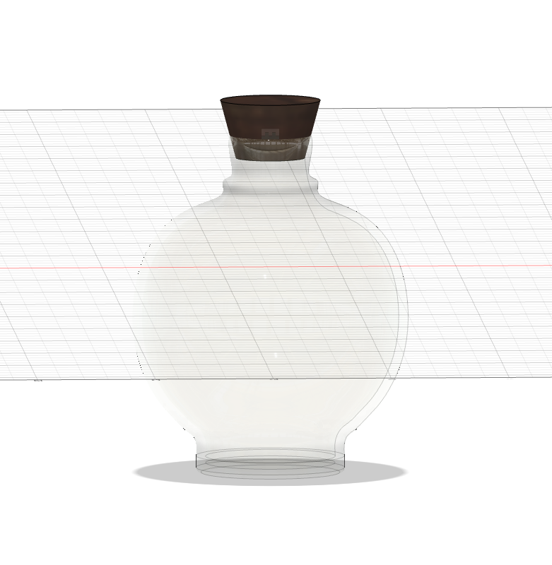
Household Bottle Model
Accurate recreation of a household bottle using revolve features and precise measurements. Captured the bottle's unique proportions, neck threading, and cap details through careful caliper measurements and parametric modeling techniques. The model demonstrates proper use of constraints and dimensional relationships.
Download Bottle .f3d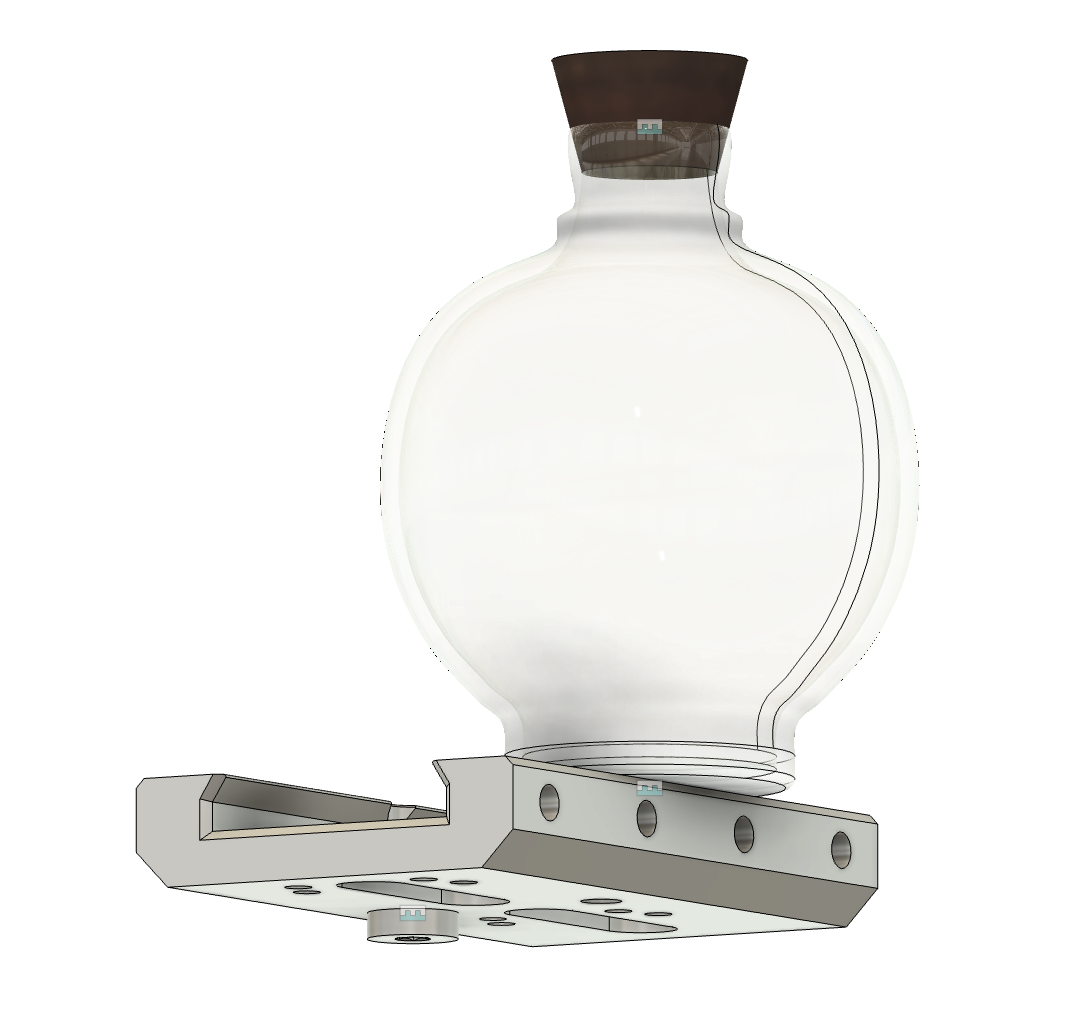
Multi-Component Assembly
Created a comprehensive assembly combining my custom-modeled M5 screw and bottle with a third component - a laser tree dovetail mount that I sourced from the GrabCAD community library.
Third Component: Laser Tree Dovetail Mount
A precision-engineered dovetail mounting system designed for laser cutting applications. This component demonstrates advanced CAD modeling techniques for creating interlocking mechanical joints commonly used in optical and precision equipment mounting systems.
View on GrabCAD Community LibrarySource: GrabCAD Community - Open CAD model repository for collaborative engineering
This exercise demonstrated skills in:
- Precision measurement with calipers
- Reverse engineering from physical objects
- Multi-component assembly creation
- Integration of external CAD models
- Proper joint and constraint application
- Assembly visualization and presentation
Download Complete Assembly
Multi-component assembly file (.f3z format)
Measurement & Modeling Insights
This exercise highlighted the importance of precision in digital fabrication. Using calipers to measure real objects taught me to appreciate tolerances and manufacturing considerations. Creating assemblies with multiple components, including external models from GrabCAD, demonstrated how collaborative design works in practice and how to integrate various sources into cohesive projects.
Reflection
This project was an excellent introduction to the CAD-to-fabrication workflow. While Fusion 360 seemed daunting at first, breaking down the design into simple geometric shapes and focusing on constraints made it manageable. The most rewarding aspect was seeing the digital model translate perfectly into a physical object that assembled correctly on the first try. This experience built confidence in both CAD modeling and understanding material properties for digital fabrication.